By the “electronics part” of a robot we mean everything inside the chassis needed to drive the motors and kick the coilgun. Note that the smartphone, although itself a sophisticated electronic device, is not included. If the smartphone is the “brain” of our robot, then the electronics inside the chassis is the “spinal cord”.
One might think that there is really not much to do here – indeed, all of the “hard thinking” seems to be done in the brain, and the spinal cord is there just to switch the motors on and off. How hard could it be? Pretty complicated, in fact.
Motors
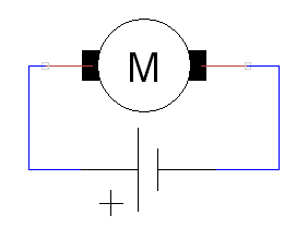
The simplest DC motor (the “brushed motor“) is a device which has two wires and a rotating shaft. If you connect the wires to a battery, the motor starts rotating – pretty simple. Here’s how that would look on a diagram:
However, this would not be sufficient for a robot – this configuration results in a continuously rotating motor, whence we would like to be able to switch it on and off. Thus, as a bare minimum, there must be a transistor and a flyback diode to allow such switching:
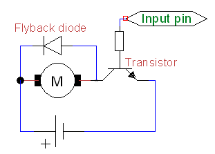
This is still not enough, though – such a configuration only allows to rotate the motor in one direction. In order to allow the robot to move backwards, the polarity of the battery must be switchable, and this would require more scaffolding around it – the H-bridge. Various schemes for implementing the H bridge exist, some more complicated, some less and we’ll not delve into this topic here. In any case, this will add at least four additional transistors to the schematics. Luckily enough, there are chips providing all of this motor driving logic in a single package: motor drivers. Those would typically include an H-bridge together with some other useful functions, such as current monitoring to prevent overheating.
But that’s still not all of it. The H-bridge would let us switch motor both ways, but how do we control its speed? The trick here is to use pulse width modulation (PWM) for the input signal. I.e. instead of switching the “input pin” to “on” and simply letting the motor rotate at maximum speed, we shall switch the pin on and off with high frequency. Now, if on average the pin is “on” just half of the time, the motor would rotate approximately with half the maximum speed.
Microcontroller
As a result, we need a component that will generate the PWM signal at the necessary frequency. What could it be? Certainly not the smartphone – it has no facilities for such fine-grained control and has enough other duties to attend to. Hence, we need a microcontroller – essentially an additional full-blown CPU just to drive the motors. Now using a microcontroller means that we need a way to program and communicate with it – this will add a couple of additional compulsory components to the circuit.
Bluetooth
Are we done yet? No. Remember we mentioned that the only reasonable way to communicate with the smartphone is Bluetooth. Thus, we shall need a Bluetooth communication module. This is mounted on a separate board and will be communicating with the controller using the UART protocol.
Coilgun
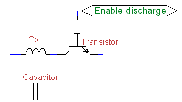
Are we done yet? No. Remember the coilgun? In order to make the solenoid jerk (and thus kick the ball) we need to apply voltage to the coil in the same way as we did with the motor on the first figure above. However, this time this will not be battery voltage – the battery voltage is too low to provide sufficient current. Instead, we shall have a separate large capacitor, that will discharge into the coil. Conceptually:
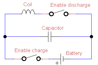
Of course, this diagram is incomplete. Once the capacitor has discharged, it has to be re-loaded again from the battery. Conceptually:
Finally, in order to charge the capacitor to high voltages, we shall need to convert the 11V battery voltage to something higher, perhaps 100V or so. To do that, we need a voltage transformer together with a DC to AC converter to make it work (you can only increase voltage of alternative currents). Thus, omitting some more details, the coilgun requires a circuit like the following:
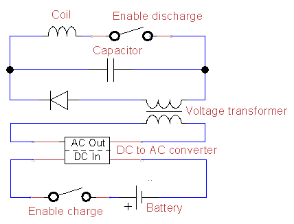
The coilgun charging/discharging algorithm is probably simple enough to be implementable without the need for a separate microcontroller, however doing it using a microcontroller is so much easier that we can use one here too.
Putting it all together
Are we done yet? Well, there are still a lot of small details (a fused power regulator, an IR ball detector, Hall rotation sensors on the motors), but in general that’s it. Here’s the high-level overview of the “spinal cord” for our robot:
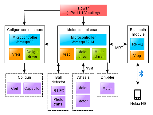
One possible indicator of the complexity of this assembly is its price. Although we shall discuss the budget in a later post, so far just take my word for it – the configuration presented above costs somewhere around €200 or more. This assumes two reasonable motors (€30 a piece at least) and a normal battery (also at least €30), yet is still a conservative estimate, which does not even include experimentation or burned parts.