The parts of the robot, that have turned out to be one of the trickiest for us, were the motors. There are three motors in our robot – two for the wheels and one for the dribbler, and all of them have been causing headaches.
Choosing the Motors
The variety of motors one can choose for the wheels of a robot is staggering. How to choose the right one? Here’s how we went about it.
The first decision we had to make is whether to use a brushless vs brushed motor. The former type is typically more powerful, more expensive, and requires somewhat more experience to operate. The latter type is what most would call a “usual” motor. Having no prior experience with brushless motors and no desire to spend extra money, we went with the simpler option.
Next, we have to pick a particular motor. Two main functional characteristics play a role here:
- Motor rotation speed – this will specify the max speed at which the robot will be capable of moving.
- Motor torque – this will define the acceleration the robot will be capable of achieving.
The theory goes approximately as follows. Start by finding the necessary rotation speed. We know that the diameter of the wheels of our robot is 6cm. We would like the robot to be capable of moving at a maximum speed of about 1 m/s. That means, the motor must be capable of rotating with speed 1 / 0.06π ≈ 5.3 revolutions per second, i.e. about 320 rpm. If we give it a little slack, we might be looking for a motor with free rotation speed of about 350-450rpm.
Next, let us compute the torque. Ideally, we might be willing for our robot to be capable of accelerating to the speed of 1m/s in about half a second, i.e. the maximum acceleration for the robot must be about 2m/s². The weight of our robot, fully assembled, is about 3kg, hence the motors will need to provide a force (F=ma) of at least 3·2 = 6 Newtons. In particular, 3 Newtons is the contribution that we expect from each motor. We also have to account for friction, and here we just blindly say we need about twice the force, i.e. 6 N from each motor. If our wheels would have a radius of 1 meter, we would need a motor with a torque of exactly 6 N·m to achieve that. Our wheels have a radius of 3cm, however, hence we would like a motor with a torque of about 6·0.03 = 0.18 N·m. Depending on the manufacturer, the motor may either be specified in terms of “rated torque” – this is a constant torque the motor is capable of providing for long periods of time, or “stall torque” – this is the maximum torque the motor provides when stalled. The stall torque is typically at least twice the rated torque, hence, according to our computations above, we might want a motor with a rated torque about 0.2 N·m or a stall torque at least 0.4 N·m.

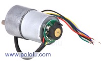
After having scouted the web from end to end, we ended up ordering a pair of these and a pair of these motors from Pololu. Besides fitting our specification, the motors have a reasonable size (some alternatives were inconveniently large to fit into the robot) and have a rotary encoder built-in, which is a feature worth paying a couple of extra euros for. Pololu also sells useful accessories, such as wheels and wheel attachment hubs, which we also ordered. It turned out the attachment hubs we chose were not suitable for the 6cm Pololu wheels, though, so we ended up lathing our own wheels but still using the tires.
The Motor Driver Problem
The important feature of a motor is its stall current. This is the current that the motor consumes when stalled, i.e. exerting maximum torque. This happens when the motor is just about to start rotating, when someone prevents the motor from rotating freely (e.g., the robot has bumped into a wall) or when the robot is trying to accelerate. The motors we ordered have their stall current specified at 5A. However, the motor drivers we had to use on our motor control PCB (designed last year for Tartu’s last year’s robots), were only meant for 2.8A or smaller currents. (In case you already forgot, this post explains what is a motor driver). “Ah well, let’s just try and see what happens, maybe the drivers will just burn down”, we thought, and we tried. Unfortunately for us, the drivers did not burn down.
They kind-of worked, but worked badly. In order to run the motors at smaller speeds we had to use weird hacks, which are not worth delving into here, and in the end, the motors still wouldn’t behave predictably. After about a month of suffering and making us come up with ugly hacks, the drivers did finally burn down, and it was good. Because by that time we have already ordered a new, more powerful pair of drivers, and needed that final push to have those installed. As soon as we got the normal drivers set up, motors started working as necessary, and life became beautiful again.

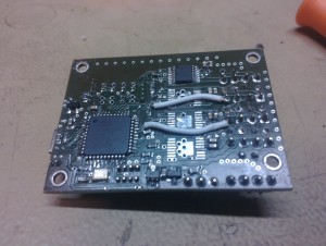
The picture below shows the lower side of our motor control PCB. The three empty spots are the places where the three original motor drivers have been (the board was originally designed to accomodate four drivers, to be used with four-wheeled robots). One of the drivers burned down when we touched a working robot with a screwdriver (separate story). Two other ones burned for some reason later. The last driver is still sitting there, and it was used to control the dribbler motor, but eventually it also burned.
The moral of this story is simple: if you use powerful motors, use powerful motor drivers.
The Dribbler Motor Problem
As mentioned above, we were using the remaining driver to control the dribbler motor (so that it would be possible to choose the speed at which it would be rotating). However, we had bad luck with this one too. Despite the fact that the dribbler motor was not trying to consume too much current, the driver for it managed to burn down three times for no clear reason (some local gurus suspect that the motor was too “low-quality” for the driver, in the sense that its brushes produced too much spark discharges when switching). So in the end, we got tired of replacing the driver over and over and had the dribbler motor connected directly to the battery via a button. It was a very good choice and I am sorry we didn’t make it in the very beginning. So let me leave you another suggestion, dear reader: if you have a choice between a simple button and a complicated electronic microchip (such as a motor driver) strongly prefer the former!
The last remark is in order. Some of the Tartu’s other teams tried using brushless motors for the dribbler (simply because those were available), but as far as I’ve seen this has caused them way more trouble than it was worth. So if you, dear reader, plan on making a soccer robot, do not use a brushless motor for the dribbler. Just take any generic reasonably-sized brushed motor that you will find lying around in the lab, connect it with a button, and that’s it, you’re done. Tartu team Sidi had it done this way and, it seems, did not have any problem with their dribbler at all.
Once the motors are connected and running, we must somehow control them from the microcontroller. We’ll leave it as a topic of a later post.