Monthly Archives: November 2011

Setting up the Camera


Camera and image processing are crucial components of a successful soccer robot. Consequently, before we could even start to build our robot we had to make sure the camera of the N9 won’t bring any unexpected surprises. In particular, the important questions were:

  • Is the angle of view of the camera reasonably wide? Can we position the camera to see the whole field?
  • What about camera resolution. If we position a ball at the far end of the field (~5 meters away) will it still be discernible (i.e. at least 3-4 pixels in size)?
  • Can it happen that the frames are too blurry when the robot moves?
  • At what frame rate is it possible to receive and process frames?

Answering those questions is a matter of several simple checks. Here’s how it went back then.

Resolution and Angle of View

The camera at N9 is capable of providing video at a framerate of about 30Hz with different resolutions, starting from 320×240 up to 1280×720. Among those, there three options which make sense for fast video processing: 320×240, 640×480 and 848×480. The first two are essentially equivalent (one is just twice the size of the other). The third option differs in terms of aspect ratio, and its horizontal and vertical angles of view. The difference is illustrated by the picture below, which shows a measure tape shot from a distance of 10cm.

Different angles of view

We can see that the resolution 848×480 provides just a slightly larger vertical angle of view than 640×480 (102mm vs 97mm) at the price of significantly reduced horizontal angle of view (65mm vs 86mm). Consequently, we decided to stick with the 640×480 resolution.

Camera positioning
Phone mounting angle

From the picture we can also estimate the angle of view, which is 2*arctan(97/200) ~ 52 degrees vertical and 2*arctan(86/200) ~ 46.5 degrees horizontal. Repeating this crude measurement produced somewhat varying results, with the horizontal angle being as low as 40 and the vertical as large as 60 degrees.

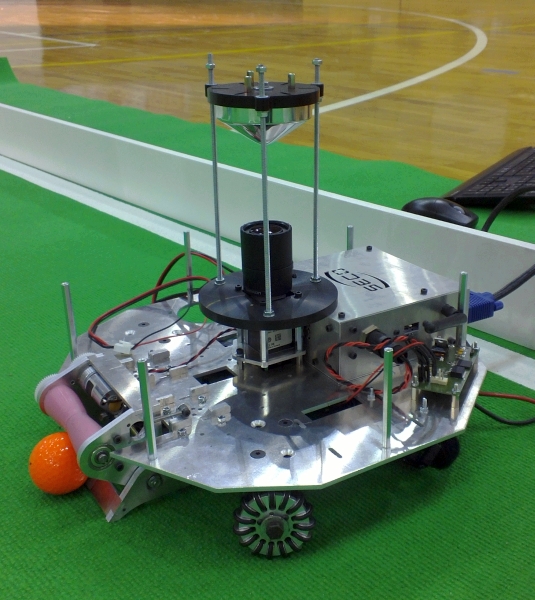
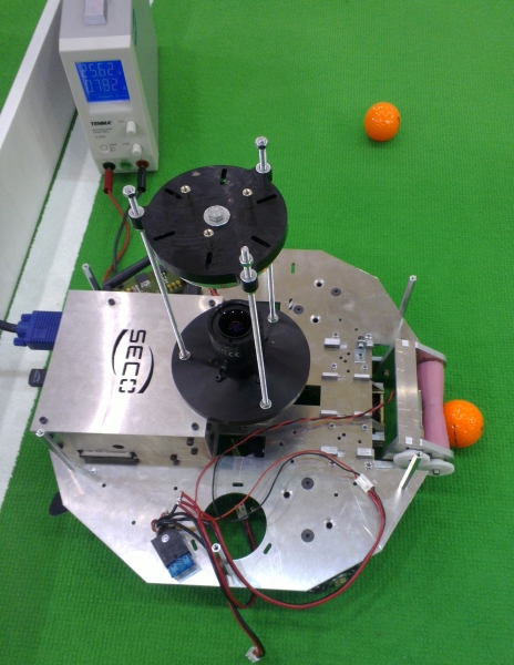
Knowledge that the vertical angle of view is 60 degrees suggested that the phone should also be mounted at around 60 degrees – this provided the full view of the field. As we also needed to see the ball in front of the robot, we had to mount the phone somewhat to the back.

Image Processing Speed

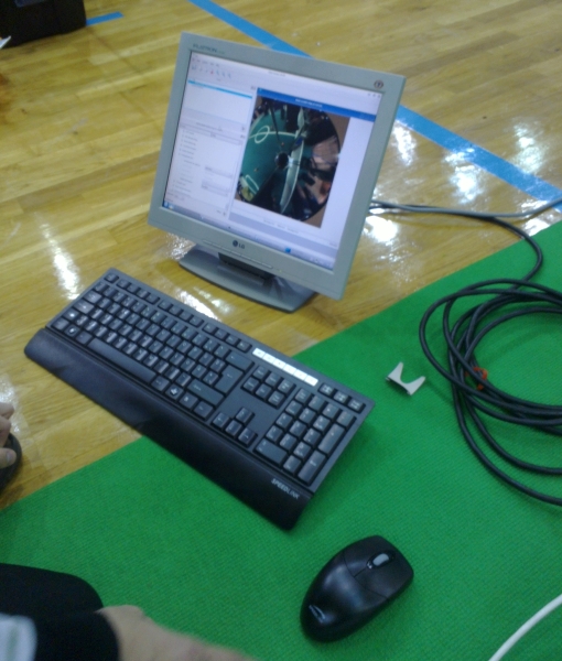
The first code we implemented was just reading camera frames and drawing them on the screen. The code could run nicely at 30 frames per second. Additional simple image operations, such as classifying pixels by colors also worked fine at this rate. Something more complicated and requiring multiple passes over the image, however, could easily drag the framerate down to 20 or 10 fps, hence we knew early on that we had to be careful here. So far it seems that we managed to keep our image processing fast enough to be able to work at 25-30 fps, but this is a topic of a future post.

Camera Speed

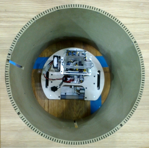
One reason why the Playstation 3 Eye camera is popular among Robotex teams is that it can produce 120 frames per second. And it is not the framerate itself, which is important (it is fairly hard to do image processing at this rate even on the fastest CPUs). The important part is that the frames are shot faster and thus do not blur as much when the robot moves. So what about our 30 fps camera? Can it be so blurry as to be impractical? We used our NXT prototype robot (at the time, we did not have our “real” robot, not even as a 3D model) and filmed its view as it drove forward (at 0.4 m/s) or rotated (at about 0.7 revolutions per second). The result is shown below:

Moving forward
Moving forward
Rotating
Rotating

The results are quite enlightening. Firstly, we see that there is no blurring problems with the forward movement. What concerns rotation, however, it is indeed true that even for a moderate rotation speed, anything further away than 50cm or so blurs to be indistinguishable. It is easy to understand, however, that this is not so much a limitation of a 30fps camera but rather a property of rotation itself. At just one revolution per second, objects even a meter away are already flying through the picture frame at 6.28 m/s. Even a 120fps camera won’t help here.

Size of the Ball in Pixels

OK, next question. How large is the ball at different distances? To answer that, we made a number of shots with the ball at different distances from the camera and measured the size of the ball in pixels. The results are the following:

Distance to ball (mm) 100 200 300 400 500 600 700 800 900 1000
Ball diameter in pixels (px) 190 105 70 55 45 37 33 29 26 22
Distance vs Pixel size

This data can be described fairly well using the following equation (the reasons for this are a topic of a later post):

PixelSize = 23400/(21.5 + DistanceMm)

Two observations are in order here. Firstly, a ball at distance 5m will have a pixel size of about 4.65 pixels, which not too bad. Note that it would be bad, though, if we were to use a resolution of 320×240, as then it would be just 2 pixels. Add some blur or shadows and the ball becomes especially hard to detect. Secondly, and more importantly, if we decide to use such an equation to determine the distance to the ball from its pixel size, we have to expect fairly large errors for balls that are further away than a couple of meters.

So that’s it. Now we’ve got a feel of the camera and ready for actual image processing.

RoboCup

Tallinn’s Robotex competition is about a single robot trying to hit all balls into the goal. Its “older brother”, the RoboCup, is about many robots chasing one ball, just like in real soccer. Doesn’t it look amazing?

Telliskivi’s robotic siblings/colleagues/opponents, part IV – Tallinn teams

Yesterday we had a chance to go to Tallinn to “practice” in the same room and with the same lighting that will be during the actual competition. There was also a “test competition” on which our robot, who lacked most of the relevant algorithmic logic, did not score a single goal. None the less, it could practice driving along the field in random directions, fighting for the ball with an opponent, and shooting a ball in the wall of the playing field, having confused it with a goal.

In the meantime, I made a couple of shots of the other robots (by IT college and TTU temas). Please excuse me for not being capable of properly identifying them. If you happen to know the names, do tell me, I’ll update the post. I might also have missed some of the robots from yesterday’s event.

Telliskivi’s robotic siblings/colleagues/opponents, part III – Advanced league

The second group of guys in Tartu are the “gurus”. They have already done at least one Robotex, and their current aim is not so much to make a baseline working device, but rather to create something fun and unusual. This takes them way more than a couple of months.

First is team Nasty, who are making an extra-cute tiny robot with a hyperbolic mirror (this way one camera can see the whole field). Their robot design was even published in a SolidWorks-themed magazine (lost the link to it, sorry).


Team Nasty robot "Mall2"
Mihkel showing off Mall2
Ramses vs Mall2
Ramses vs Mall2

If team Nasty is aiming for a smallest possible size, another team (not sure about the name), is making a hyperbolic-mirror based robot which is as large as it can get. Its weight is going to be close to the upper allowed limit of 8kg. Unfortunately, I did not manage to get a shot of this robot in its assembled shape, but here’s the view of its lower base plate during maintenance:

The baseplate of a heavyweight robot

The third guru here is Matis, who is working on something which has huge wheels, two kilowatt-or-so powerful motors and can drive around at 5-10 m/s, if not more. This robot is in its early stages yet, so it does not have anything besides the motors and wheels yet. As usual, I could not even get a good shot of it

Chassis of Matis's robot

Finally, there is a robot that, I am sure, is going to be everyone’s favourite, once it steps up onto the Robotex field (which, unfortunately is not happening this year yet). This is the legged spider by team “polügoon Z”.

Spider robot
Spider robot
Spider robot
Spider robot
Omnivision camera on the bottom of the spider

The best part of it is that the Spider robot team maintains an awesome blog, covering everything about their robot’s insides and outsides.

Telliskivi’s robotic siblings/colleagues/opponents, part II – Beginners league

There are two types of Robotex robot builders in Tartu – the beginners and the “old sharks”. The first ones are those guys who come in September with no previous experience, and struggle with the simplest things to have the simplest possible solution working by the end of November, when the competition happens. We are one of such teams. Besides us, there are beginner-league teams named Spirit, Sidi, and EKRS. Although I’m not good at being with a camera at the right moment in the right place, I did manage to get some shots.

Ball detector

One sensor that has not been mentioned previously is the “ball detector”. The ball detector helps us to easily detect when a ball has been “caught” by the dribbler and is in a position ready to be hit by the kicker.

The detector is implemented using a classical opto-isolator idea. On one side of the dribbler we put a small infrared LED, that will be constantly emitting infrared light. On the other side of the dribbler, we attach an infrared photodiode (or, to be more precise, we actually use a slightly more sophisticated breakbeam sensor). Now, whenever there is no ball in the dribbler, the sensor will be “seeing” the light from the IR led and produce an “off” (i.e. 0V) signal on one of its pins (note that a conventional photodiode would work the other way around). Whenever a ball comes into the dribbler inbetween the LED and the sensor, it will hide the light from the diode, the signal will go up to “on” (i.e. 5V), and this can be sensed by the controller.

Of course, in theory we could detect the fact that the ball is in the dribbler purely from the camera image, but having a dedicated ball detector sensor is easy and convenient.

Ball detector: IR LED
The black dot under the dribbler shaft is the infrared LED
Ball detector: Photodiode
On the other side, there is a photoelement

Coilgun

A coilgun, is the part responsible for kicking the ball. As you might remember from an earlier post, it consists of a solenoid (coil), a capacitor, a metal bar, a spring and a controller circuit.

Coilgun

The Theory

There are thousands of tiny details that must be decided upon in order to make a coilgun: you need to choose the material of the metal bar, the force of the spring, the parameters of the wire comprising the coil, the diameter and number of turns of the coil, capacity of the capacitor and its operational voltage. Ironically, despite the abundance of those details, in the end there is just one simple thing that matters: the coilgun must kick the ball strongly enough to send it to the opponent’s goal.

Understanding how each of the above parameters influences the strength of the kick requires patience and a solid knowledge of high school physics and beyond. We won’t go into this here, but here’s a brief overview of the main issues that matter:

In order for the kicker bar to jerk strongly enough, the coil must produce a strong magnetic field.  In order to produce a strong field, strong current must flow through the coil, the coil should have many turns and the turns should preferably be small. In order to produce the strong current over a long wound wire we need higher voltage and a large capacitor.

On the other hand, an excessively strong current would melt the wire, and excessively strong voltage would produce sparks, and an excessively large capacitor would be heavy, expensive and dangerous. In the end, there is a kind of balance between “small and light” and “strong and heavy”.

Although in principle it should be possible to come up with a “theoretically perfect set” of parameters which result in the lightest possible, yet functional coilgun, we went along a simpler route of reusing the practical knowledge of our predecessors and intuition:

  • We use a 1500uF capacitor to be charged at 250V. The 1500uF number comes from the fact that such a capacitor was available and the 250V number is related to the coilgun control PCB from the previous year’s Tartu teams, which we could reuse.
  • We have a coil wound of 1000 turns made of 0.4mm copper wire. The wire was chosen fairly arbitrarily and the number of turns was selected so that the total coil resistance would be somewhere around 4 Ohm. At 250V this would result in a discharge current of around 60A (a “good current for a coilgun”, according to the knowledge of local gurus).
  • The 1500uF capacitor charged to 250V can theoretically discharge at this current for at least 6ms, which turns out to be sufficient for the metal bar to make a strong kick.

The resulting coilgun works fine, but it is so strong that it could have been way lighter. If you, dear reader, happen to be in the mood for doing some exciting physics exercises, I dare you to use science and come up with a better set of coilgun parameters.

The Practice

To make the actual coil we used an old electromagnet of unknown origin (perhaps a lock or something) which was kindly provided to us by our fellow Tartu team EKRS.
Old electromagnet, disassembled
We replaced the wire with our own (on one of the previously posted videos you may actually find a hidden moment, where Reiko is seen in the process of winding the coil using a lathe), added a metal box (which you can see being machine-milled on that same video), and attached everything to the first floor of our robot.
Coilgun in the attachment box (model)
Coilgun, attached
Coilgun, attached

Unfortunately, we do not have a lot of “in progress” photos of the coilgun making. Here is, however, a nice view of the EKRS robot body together with a coilgun control PCB (same as ours), a large capacitor (ours is slightly smaller) and a coil while it was still being developed:

EKRS coilgun development

 Another Tartu team had their capacitor explode with a loud and scary boom. So, dear reader, please beware: large capacitors can explode easily and violently when connected incorrectly, used with invalid voltage, or damaged:

Exploded capacitor
Exploded capacitor

And finally, here’s a video demonstrating the Telliskivi coilgun in action: