The Robotex course requires participants to present their progress once each week. This automatically imposes an iterative approach to development – instead of working for a long time and coming up with a final design for the robot, we had three iterations – two preliminary drafts and the final one. The design was made using SolidEdge first (because Taavi was more familiar with it) and SolidWorks later (because Reiko was more familiar with it). Both programs are well-known industrial CAD packages. The former provides a student licence to anyone. With the latter, University of Tartu has a special arrangement for student licensing.
Here I must admit that my previous encounters with mechanical drafting was a long time ago, in high school, where we were supposed to manually draw various hypothetical 3D bodies on A4 paper and write labels using a strictly defined font. I recollect we even made one part manually according to that draft. I never enjoyed nor appreciated the course, and in fact never even understood the need for this whole drafting business: building things seemed so much easier without it. Well now I finally got it. It took me 14 years to understand the obvious. You draft something and then let other people manufacture according to it. Duh.
OK, back to the robot. Our first draft was that of a “brick on wheels” (note that this is using the N950, as this was before we got the N9). The dribbler and kicker are not present, but room is left for them. The electronics attachments are not present either, but are already planned to go onto the second floor.

In the second iteration, Taavi decided to position the camera higher up, on a tower. This would shift the weight backwards:

Finally, the third and the last iteration was completed by the beginning of October.

A couple of simplifications were introduced here. Firstly, the smartphone tower is now connected to the second floor – this makes it easier to assemble the robot. Secondly, the wheels are now directly mounted onto motor shafts. This means that the whole weight of the robot goes on those shafts and if our robot would have been too heavy, this might not have been a good solution. Fortunately, this is not a problem.
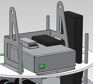
Note the pluggable electronics module box, designed by Reiko:
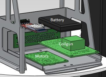
The small box in the upper right is the Bluetooth module, the black bricks are batteries (why two? stay tuned for a later post). The big box below contains the printed circuit boards for controlling the motors and the coilgun:
Most of the details of the chassis are to be laser-cut from aluminum (first floor, tower, electronic box) and plastic (everything else). The aluminum cutting was ordered in Metec, and plastic cutting – in Tööstusplast.

