Now that we’ve figured out how to operate a motor, let us describe the second important electro-mechanical component of the robot – the coilgun. Previously, we have already discussed briefly the general idea and its mechanical realization. What remains are the minor implementation details.
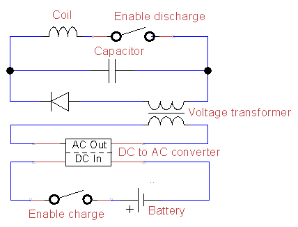
Recollect that the general scheme of a coilgun (somewhat simplified, of course) is the following:

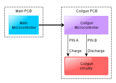
In order to make this scheme operable, we must replace the switches “Enable charge” and “Enable discharge” with transistors, connected to a microcontroller. In our case we had a separate microcontroller operating the coilgun, which means that we also needed to establish communication between the main controller and the coilgun controller. The resulting scheme is then, in principle, the following:

The task of the coilgun microcontroller is rather simple: receive signals from the main microcontroller and set its output pins A and B accordingly. Our robot’s coilgun controller implemented essentially the following four functions:
void enableCharge() {
    set_pin(PIN_A, 1); // Enable charging of the capacitor
}

void disableCharge() {
    set_pin(PIN_A, 0); // Disable charging of the capacitor
}

void kick() {
    set_pin(PIN_B, 1); // Start discharging capacitor
    delay_ms(5);       // Wait 5ms
    set_pin(PIN_B, 0); // Stop discharge
}

void dischargeSlowly() {
    for (int i = 0; i < 20; i++) {
       set_pin(PIN_B, 1);
       delay_ms(1);       // Discharge a bit
       set_pin(PIN_B, 0); // Let the kicker be pulled back
       delay_ms(5);
    }
}
The last function (dischargeSlowly) is there to allow a graceful shutdown of the robot, where the capacitor discharges without the kicker having to jerk hard.
The communication between the main microcontroller and the coilgun may be implemented using various protocols. Originally, our coilgun PCB was meant to be controlled via the SPI protocol, but during one of the mishaps the corresponding pins burned down and we ended up using a simpler solution, where three output pins of the main controller were directly connected to the input pins of the coilgun board. A command was sent by specifying its code using the first two pins and sending a pulse on the third one.
If you will ever be making your own coilgun…
It must be noted that the coilgun was perhaps the most complicated electromechanical part of our robot and as this blog tries to make things sound as simple as possible, it sweeps some details under the carpet. If you, dear reader, for some reason, will be going to build a coilgun yourself (perhaps when taking part in one of the next Robotex/Robocups), take your time to skim through the following sites first:
- Team Nasty’s robot “Mall 2” coilgun PCB specs,
- Helpful tech reports by the Eindhoven RoboCup teams: (one), (two),
- http://coilgun.info/
Safety notes
In order for the coilgun to be capable of hitting the ball with appropriate force, it must contain a reasonably large capacitor, and large capacitors can be dangerous. A 1.5mF capacitor, when charged to 250V, stores 0.0015·250² = 93.75 Joules of energy – something comparable to an energy of a 10kg brick falling from 1 meter’s height. If such a capacitor short-circuits, all this energy can get released in a single explosion, and you do not want your fingers to be nearby. Even if your fingers are spared, your electronics can get irreparably damaged.
In order to avoid a capacitor explosion (there were at least three of those among the Tartu teams during the two months leading to Robotex), keep in mind the following:
- You should not short-circuit a capacitor. Obviusly, this will result in an immediate discharge of all its energy, which means an explosion. Of course, no one ever short-circuits a capacitor deliberately, but it is unexpectedly easy to do it accidentally.
- You should never physically damage a capacitor. A damaged capacitor may short-circuit internally and explode for no apparent reason later on. Hence, if a capacitor falls on concrete floor once, beware when reusing it.
- A capacitor must be used with appropriate voltages and connected in accordance to its polarity. Invalid voltage or polarity may damage it internally, which will lead to internal short-circuit.
To be more specific, here are some educational stories:
- Some guys were debugging their PCB using a digital oscilloscope and touched a “positive” end of the capacitor with a “ground” probe of the oscilloscope. As a result, there was a short circuit through the ground, boom.
- Other guys were trying to fix something using a screwdriver right on a working robot with a charged capacitor. Screwdriver touches the metal cover of the robot (which most probably was connected to the “ground”. of the electronics somewhere). Next, either due to a static discharge from the screwdriver, or due to its external potential acting to inversely polarize the capacitor, the boom happens.
In fact, touching a working robot with a metal object is a bad idea for many more reasons. The two times when our team has managed to mess up the electronics were both related to someone trying to touch a working robot with a metal object. So beware. - Yet other guys have attached a capacitor to their robot using just Velcro tape. The robot starts spinning, the tape does not hold, the capacitor slips off and touches some of the electronics with its terminals. No boom, but all of the electronics burned down.