Knowing that a certain orange blob on the picture corresponds to a ball does not help us much unless we know how to drive in order to reach it. In order to be able to do that, we must compute where exactly this ball is located with respect to the robot. Thus, the second important basic component of our vision subsystem (after the color recognition/blob detection module) is the coordinate mapper.
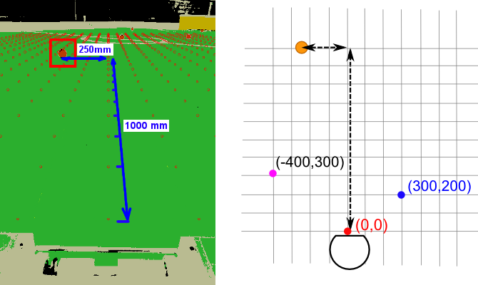
We shall assign coordinates to the points of the field. Coordinates will be local to the robot (we shall therefore refer to them as “robot frame coordinates“). That means, the origin of the coordinate system (the point (0, 0), red on the image above) will will be fixed directly in front of the robot. The point with coordinates (300, 200) will be 300mm to the right and 200mm to the front (the blue point on the image above), etc.
With the coordinate system fixed, each pixel on the camera frame uniquely corresponds to a point on the field with particular coordinates. The task of the coordinate mapper is to convert from pixel coordinates to robot frame coordinates and vice-versa.
Camera projection
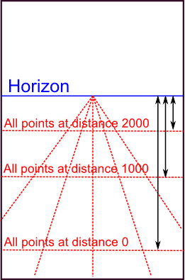
How do we perform the conversion? Let’s start with the distance, i.e. the Y coordinate. If you examine the typical view from our robot’s camera, you will easily note that the vertical coordinate of a pixel uniquely determines its distance from the robot. Points on the “horizon line” lie at infinite distance, and become closer as you move lower along the picture. The relation between the pixel’s vertical coordinate (counted from the horizon line) and actual distance to it is an inverse function:
ActualDistance = A + B/PixelVerticalCoord,
where A and B are some constants.
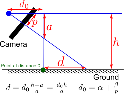
I will not bore you with the proof of this fact. If you are really interested, however, you should be able to come up with it on your own after reading a bit about the pinhole camera model, the perspective projection, and meditating on the following figure (here, p is the pixel vertical coordinate as counted from the horizon line and d is the actual distance on the ground).
Finding the X coordinate (i.e. the distance “to the right”) is even easier. Note that as you approach horizon, the pixel-width of a, say, 100mm segment, decreases linearly.
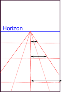
That means that the relation between a pixel’s horizontal coordinate and the corresponding point’s coordinate on the ground must be of the form:
ActualRight = C * PixelRight / PixelVerticalCoord
where C is some constant again.
Finding the constants
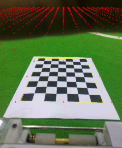
Once we’re done with the math, we need to find the constants A, B, C as well as the pixel coordinate of the horizon line to make the formulas work in practice. Those constants depend on the orientation of the camera with respect to the ground, i.e. the way the camera is attached to the robot. For robots that have their cameras rigidly fixed it is typically possible to compute those values once and forget about them. Telliskivi’s camera, however, is not rigidly fixed, because the smartphone can be taken out from the mount. Thus, every time the phone is repositioned (or simply nudged hard enough to get displaced), we need to recalibrate the coordinate mapper by computing the A, B and C values, corresponding to the new phone orientation.
To do the calibration, we need to “label” some pixels on the screen with their actual coordinates in the robot frame. The easiest approach for that is to lay out a checkerboard pattern (or any other easily detectable pattern) printed on a piece of paper in front of the robot. After that, a simple corner detection algorithm can locate the pixels, which correspond to the four corners of the pattern. As the dimensions of the pattern are known and it is laid out at a fixed distance from the robot’s front edge, the actual coordinates, corresponding to the corner pixels are also known. Hence, putting those values into the equations above lets us compute the suitable values for the A, B and C constants and this completes the calibration.
On coordinate mapping precision
It is worth keeping in mind that due to the properties of perspective projection, coordinates of faraway objects computed using the formulas presented above can be rather imprecise. Indeed, for objects further than 3-4 meters, an error by a single pixel can correspond to a distance error of more than 20 cm. Such pixel errors, however, happen fairly often. For example, a shadow may confuse the blob detector to not include the lower part of a ball into the blob. Alternatively, the robot itself may tilt or vibrate due to the irregularities of the ground – this shakes the camera and shifts the whole picture by a couple of pixels back and forth. Luckily, this discrepancy is usually not an issue as long as our main goal is chase balls and kick them into goals. If better precision for faraway objects were necessary, however, it would be possible to achieve by carefully tracking the objects over time and averaging the measurements.
Summary
To summarize, this is how the actual declaration of our coordinate mapping module looks like (as usual, with a couple of irrelevant simplifications):
class CoordinateMapper {
private:
    // Mapping parameters we've discussed above
    qreal A, B, C;
    // Screen coordinates of the midpoint of the horizon line
    QPointF horizonMidPoint;
public:
    // Load parameters from file / Save to file
    void load(const QString& filename);
    void save(const QString& filename) const;

    // Initialize parameters from the four pixel coordinates
    // of a predefined pattern lying in front of the robot.
    bool fromCheckerboardPattern(QPoint bottomLeft, QPoint topLeft,
                                 QPoint bottomRight, QPoint topRight);

    // The main conversion routines
    QPointF toRobotFrame(const QPointF& screen) const;
    QPointF toScreen(const QPointF& robotFrame) const;

    // Paints a grid of points visualizing current mapping
    // (you've seen it on the pictures above).
    // Useful for debugging.
    void paint(QPainter* painter) const;
};
In addition, we also have a CheckerboardDetector helper module of the following kind:
class CheckerboardDetector {
public:
    void init(QSize size);                 // Initialize module
    void processFrame(const uyvy* frame);  // Detect pattern
    void paint(QPainter* painter) const;   // Debug painting

    bool failed() const;                   // Was detection successful?
    const QPoint& corner(CornerId which) const; // Detected corners
    enum CornerId { TOPLEFT, TOPRIGHT, BOTTOMLEFT, BOTTOMRIGHT };
private:
    // ... omitted ...
}