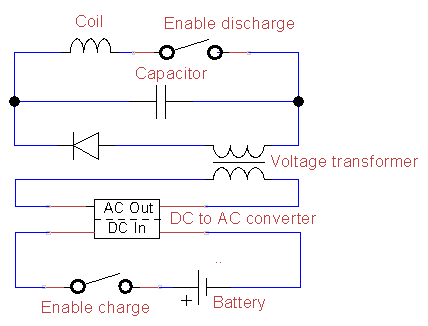
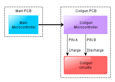
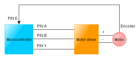
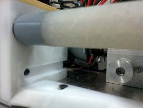
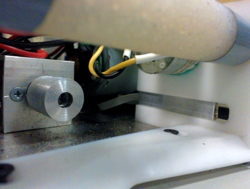
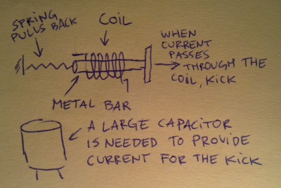
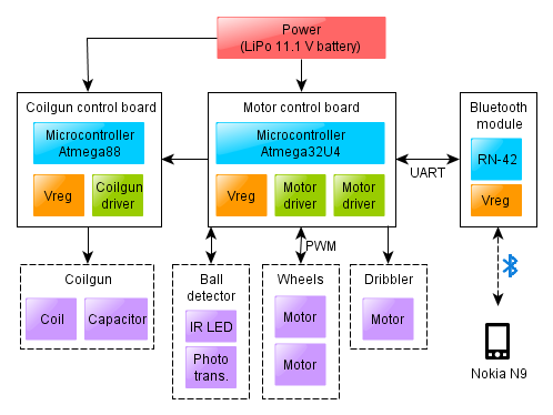
OK, so we have made the chassis with a couple of motors, a coilgun, a ball detector, and the electronic circuitry to control all of this. This makes up the “body” of our robot and what remains is the “brain”. As you should know already, the brain in our case is a Nokia smartphone. The brain needs to be constantly communicating with the body – sending movement and shooting commands and reading ball sensor and perhaps motor sensor data. As we explained in one of the first posts, we need to use the Bluetooth protocol for such communication.
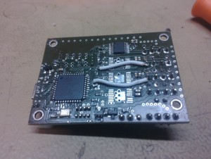
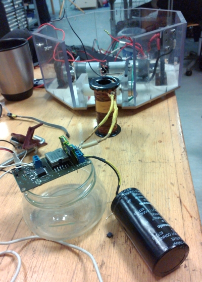
We thus had to purchase a separate module and connect it to our main microcontroller (attentive readers have already seen this module in one of the pictures). There is a fairly wide variety of Bluetooth modules available out there. Our criteria for choosing a suitable one were the following:
- The module must have an integrated implementation of the full Bluetooth protocol stack. Bluetooth is a fairly complicated set of protocols, and there are some modules which only implement parts of it. The remaining parts would have to be implemented in software (i.e. in the microcontroller) and this would make our life difficult.
- The module must use the UART protocol. This is the default serial protocol supported by our microcontroller. Most Bluetooth modules use it anyway.
- The module must have a readable datasheet. Debugging a no-name module with no reference manual is not something we look for.
- The module should be reasonably priced. Although ELFA is certainly not a place to look for “reasonably priced” things, we can use the knowledge that the cheapest module there (which happens to fit the previous criteria) costs €32.50.
- Finally, the module might have some positive reviews on the internet.
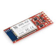
SparkFun’s BlueSMIRF Silver happened to fit all of them (especially the last one), so we ordered it and so far it has been one of the less troublesome parts of our robot. Although it does have a detailed datasheet, pretty much none of that information was even needed, because the module does most of the work itself. All the microcontroller has to do is read and write bytes over the UART pins, to which the module is attached.
To read and write over UART we borrowed the code from the Teensy UART library and added a couple of simple wrappers around the low-level uart_getchar and uart_putchar methods. After this was done, we could complete the main loop of our robot’s microcontroller:
int main() {
    // ... initialization code ...

    char buf[32];

    while (true) {
        bool success = recv_command(buf, sizeof(buf));
        if (success) execute_command(buf);
    }
}
This function, together with the interrupt handlers mentioned in the post about motor control, is essentially all there is to our main microcontroller’s code.
Serial Communication and Interrupts
If you will be implementing a similar solution, beware of one particular hidden reef. The UART communication in Atmega uses interrupts to receive bytes. That is, every time a new byte arrives on the serial port, an interrupt handler is invoked. The code in this interrupt takes responsibility of storing the received byte into a buffer for further processing. While this interrupt is in process, no other interrupts will be invoked. For example, if during the reading of a byte a motor encoder happens to send a pulse, this pulse would not get counted, simply because the controller won’t be there waiting to catch it.
This issue is even worse the other way around – if the microcontroller happens to stay “too long” in one of the other interrupts, he might simply miss an incoming byte. As a result, weird things will start happening – the command “move” might get received as “mve” or worse still, a command separator character will be missed and two commands will be concatenated into one.
There is really no good solution to this problem besides being careful and not writing code which might stay too long in an interrupt handler. At one moment we had an interrupt handler like that (the one which performed the PID computation in a timer), and it resulted in a fairly large number of communication errors. Surprisingly, the problem nearly disappeared after we rewrote the computation from 32-bit integers to 16-bit integers. It turns out that an 8-bit microcontroller can spend too much time simply adding and multiplying 32-bit numbers.
Bluetooth and Latency
A final word of warning is related to latency. Although the communication speed for a Bluetooth connection is quite good (in our case it was actually limited by the UART’s 115 kbps), the latency is not. That is, although you might easily send up to 15 000 single-character commands per second on a UART+Bluetooth connection, if you require (and wait for) a response to each command, the actual throughput can be somewhere around 30-60 commands per second.
In fact, this particular problem (and the fact that we discovered it too late to go fixing) has been one of the main reasons why our robot was somewhat “slow” during aiming in the final competition. We focused a lot on keeping the vision processing speed at 30 frames per second as this was, according to general knowledge, the hardest part to get working fast. Unknowingly, we were at the same time unreasonably wasteful in communication. Whenever robot would have the ball in the dribbler, we would query the ball sensor too often. As we would also wait for sensor query command to respond before proceeding with computation, this (rather than the dreaded vision processing!), was the reason our actual processing speed went down to about 15-20 fps every time the robot was holding the ball. Those were, however, exactly the moments when the robot was aiming for the goal and needed as high a framerate as possible.
