Now that we are done with the hardware details, let us move to the “brain” of the Telliskivi robot – the software, running on the smartphone. By now you can safely forget everything you read (if you did) about the hardware, and only keep in mind that Telliskivi is a two-wheeled robot with a coilgun and a ball sensor, that can communicate over Bluetooth.
You should also know that Telliskivi’s platform understands the following simple set of textual commands:
speeds <x> <y>– sets the PID speed setpoints for the two motors. In particular, “speeds 0 0” means “stop moving”, “speeds 100 100” means “move forward at a maximum speed”, “speeds 10 -10” means “turn clockwise on the spot”,charge– enables the charging of the coilgun capacitor,shoot– shoots the coilgun,discharge– gracefully discharges the coilgun capacitor,sense– returns 1 if the ball is in the detector and 0 otherwise.
(*Actually, things are just a tiny bit more complicated, but it is not important here).
We now add a smartphone to control this plaform. The phone will use its camera to observe the surroundings and will communicate with the platform telling it where to go and when to shoot in order to win at a Robotex Soccer game.
The software that helps Telliskivi to achieve this goal is structured as follows:
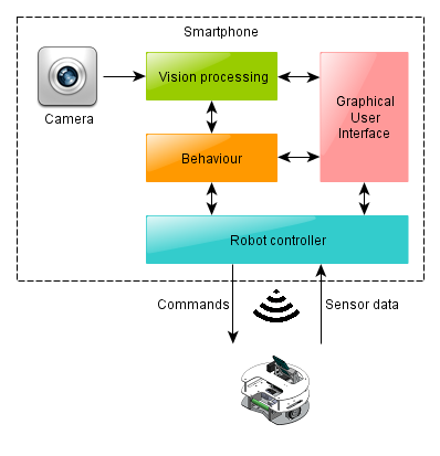
The Robot Controller
The Robot Controller is a module (a C++ class) which hides the details of Bluetooth communication (i.e. the bluez library and the socket API). The class has methods which correspond to the Bluetooth commands mentioned above, i.e. “speeds(a,b)“, “charge()“, “shoot()” and “sense()” and “discharge()“. In this way the rest of the system does not have to know anything at all how exactly the robot is controlled.
For example, a simple change in this class lets us use the same software to control a Lego NXT platform instead of Telliskivi. That platform does not have a coilgun nor a ball sensor (hence the shoot(), sense() and discard() methods do not do anything), but it can move in the same way, so if we let our soccer software run with the NXT robot, the robot still manages to imitate playing soccer – it would approach balls and desperately try to push them towards the goal. Looks funny and makes you wonder whether it is polite to laugh at physically disabled robots.
Obviously, the robot controller is the first thing we implemented. We did it even before we had Telliskivi available (we could use the Lego NXT prototype at that time).
Graphical User Interface (GUI)
The GUI is the visual interface of the smartphone app. Ours is written in QML, a HTML-like language for describing user-interfaces. Together with the Qt framework this is the recommended way of making user applications for Nokia N9. It takes time to get used to, but once you grasp it, it is fairly straightforward.
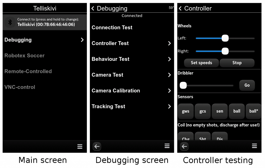
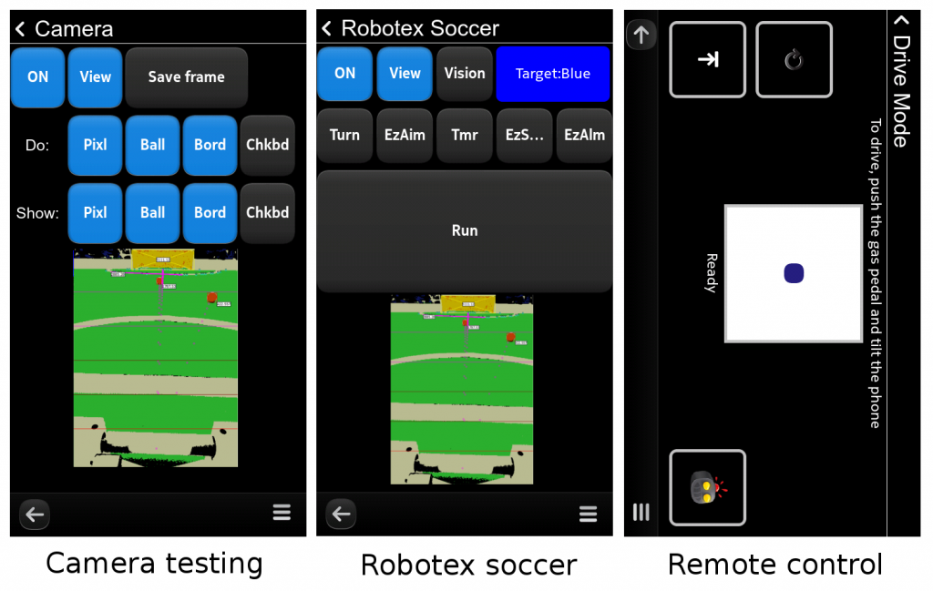
The overall concept of our UI is not worth delving deeply into – it is just a bunch of screens organized in a hierarchical manner. Most screens are meant for debugging – checking whether the Bluetooth connection works, whether the robot controller acts appropriately, whether the vision system detects objects correctly, and whether the various behaviours are behaving as expected.
In addition, there is one “main competition” screen with a large “run” button, that invokes the Robotex soccer mode and two “remote control” screens. One allows to use the phone as a remote control for the Telliskivi platform and steer it by tilting the phone (this is fun!). Another screen is meant to be used as a VNC server (so that you can log in to the robot remotely over the network from you computer, view the camera image and drive around – even more fun). For the curious, here are some screenshots:
Vision Processing
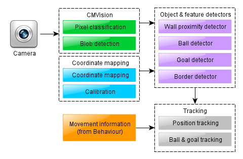
The vision processing sybsystem is responsible for grabbing the frames from the camera (using QtMultimedia), and extracting all the necessary visual information – detecting balls, goals and walls. In our case, parts of the vision subsystem were also responsible for tracking the robot’s position relative to the field. Thus, it is a fairly complex module with multiple parts and we shall cover those in more detail in later posts.
Behaviour Control
The last part is responsible for processing vision information, making decisions based on it, and converting them into actual movement commands for the robot – we call it the “behaviour controller”.
As the camera was the main sensor for our robot, we had the behaviour controller synchronized with the camera frame events. That is, the behaviour controller’s main method, (called “tick”), was invoked on each camera frame (which means, approximately 30 times per second). This method would examine the new information from the vision subsystem and act in correspondence to its current “goal”, perhaps changing the goal for the next tick if necessary. This can be written down schematically as the following algorithm:
on every camera frame do {
   visionProcessor.processFrame();
   currentGoal = behave(currentGoal, visionProcessor, robotController);
}
In a later post we shall see how depending on the choice of representation of the “goal”, this generic approach can result in behaviours ranging from a simple memoryless single-reflex robot, to somewhat more complex state machines up to the more sophisticated solutions, suitable for the actual soccer-playing algorithm.
The ROS Alternative
As you might guess, all of our robot’s software was written by us from scratch. This is a consequence of us being new to the platform, the platform being new to the world (there is not too much robotics-related software pre-packaged for N9 out there yet), and the desire to learn and invent on our own. However, it does not mean that everyone has to write things from scratch every time. Of course, there is some good robotics software out there to be reused. Perhaps the most popular system that is worth knowing about is ROS (“Robot OS”).
Despite the name, ROS is not an operating system. It is a set of linux programs and libraries, providing a framework for easy development of robot “brains”. It has a number of useful ready-made modules and lets you add your own easily. There are modules for sensor access, visualization, basic image processing, localization and control for some of the popular robotic platforms. In addition, ROS provides a well-designed system for establishing asynchronous communications between the various modules: each module can run in a separate process and publish events in a “topic”, to which other modules may dynamically “subscribe”.
Note that such an asynchronous system is different from the simpler Telliskivi approach. As you could hopefully understand from the descriptions above, in the Telliskivi solution, the various parts are fairly strictly structured. They all run in a single process, and operate in a mostly synchronized fashion. That is, every camera frame triggers the behaviour module, which, in turn, invokes the vision processing and sends commands to the robot controller. The next frame will trigger the same procedure again, etc. This makes the whole system fairly easy to understand, develop and debug.
For robots that are more complicated than Telliskivi in their set of sensors and behaviours, such a solution might not always be appropriate. Firstly, different sensors might supply their data at different rates. Secondly, having several CPU cores requires you to run the code in multiple parallel processes if you want to make good use of your computing power. Even for a simpler robot, using ROS may be very convenient. In fact, several Robotex teams did use it quite successfully.
In any case, though, independently of whether the robot’s modules communicate in a synchronous or asynchronous mode, whether they are parts of a framework like ROS or simple custom-made C++ classes, whether they run on a laptop or a smartphone, the overall structure of a typical soccer robot’s brain will still be the one shown above. It will consist of the Vision Processor, the Behaviour Processor, the Robot Controller and the GUI.
Summary
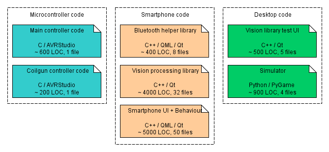
To provide the final high-level overview, the diagram below depicts all of the programming that we had to do for the Telliskivi project. This comprises:
- about 800 lines of C code for AVR microcontrollers,
- about 7000 lines of C++ code for the Vision/Behaviour code
- about 2000 lines of QML code for the smartphone UI elements.
- about 900 lines of Python code for the simulator
- about 500 lines of C++ code for the Vision test application (for the Desktop)
