One sensor that has not been mentioned previously is the “ball detector”. The ball detector helps us to easily detect when a ball has been “caught” by the dribbler and is in a position ready to be hit by the kicker.
The detector is implemented using a classical opto-isolator idea. On one side of the dribbler we put a small infrared LED, that will be constantly emitting infrared light. On the other side of the dribbler, we attach an infrared photodiode (or, to be more precise, we actually use a slightly more sophisticated breakbeam sensor). Now, whenever there is no ball in the dribbler, the sensor will be “seeing” the light from the IR led and produce an “off” (i.e. 0V) signal on one of its pins (note that a conventional photodiode would work the other way around). Whenever a ball comes into the dribbler inbetween the LED and the sensor, it will hide the light from the diode, the signal will go up to “on” (i.e. 5V), and this can be sensed by the controller.
Of course, in theory we could detect the fact that the ball is in the dribbler purely from the camera image, but having a dedicated ball detector sensor is easy and convenient.
The black dot under the dribbler shaft is the infrared LEDOn the other side, there is a photoelement
A coilgun, is the part responsible for kicking the ball. As you might remember from an earlier post, it consists of a solenoid (coil), a capacitor, a metal bar, a spring and a controller circuit.
Coilgun
The Theory
There are thousands of tiny details that must be decided upon in order to make a coilgun: you need to choose the material of the metal bar, the force of the spring, the parameters of the wire comprising the coil, the diameter and number of turns of the coil, capacity of the capacitor and its operational voltage. Ironically, despite the abundance of those details, in the end there is just one simple thing that matters: the coilgun must kick the ball strongly enough to send it to the opponent’s goal.
Understanding how each of the above parameters influences the strength of the kick requires patience and a solid knowledge of high school physics and beyond. We won’t go into this here, but here’s a brief overview of the main issues that matter:
In order for the kicker bar to jerk strongly enough, the coil must produce a strong magnetic field. In order to produce a strong field, strong current must flow through the coil, the coil should have many turns and the turns should preferably be small. In order to produce the strong current over a long wound wire we need higher voltage and a large capacitor.
On the other hand, an excessively strong current would melt the wire, and excessively strong voltage would produce sparks, and an excessively large capacitor would be heavy, expensive and dangerous. In the end, there is a kind of balance between “small and light” and “strong and heavy”.
Although in principle it should be possible to come up with a “theoretically perfect set” of parameters which result in the lightest possible, yet functional coilgun, we went along a simpler route of reusing the practical knowledge of our predecessors and intuition:
We use a 1500uF capacitor to be charged at 250V. The 1500uF number comes from the fact that such a capacitor was available and the 250V number is related to the coilgun control PCB from the previous year’s Tartu teams, which we could reuse.
We have a coil wound of 1000 turns made of 0.4mm copper wire. The wire was chosen fairly arbitrarily and the number of turns was selected so that the total coil resistance would be somewhere around 4 Ohm. At 250V this would result in a discharge current of around 60A (a “good current for a coilgun”, according to the knowledge of local gurus).
The 1500uF capacitor charged to 250V can theoretically discharge at this current for at least 6ms, which turns out to be sufficient for the metal bar to make a strong kick.
The resulting coilgun works fine, but it is so strong that it could have been way lighter. If you, dear reader, happen to be in the mood for doing some exciting physics exercises, I dare you to use science and come up with a better set of coilgun parameters.
The Practice
To make the actual coil we used an old electromagnet of unknown origin (perhaps a lock or something) which was kindly provided to us by our fellow Tartu team EKRS.
Old electromagnet, disassembled
We replaced the wire with our own (on one of the previously posted videos you may actually find a hidden moment, where Reiko is seen in the process of winding the coil using a lathe), added a metal box (which you can see being machine-milled on that same video), and attached everything to the first floor of our robot.
Coilgun in the attachment box (model)
Coilgun, attached
Unfortunately, we do not have a lot of “in progress” photos of the coilgun making. Here is, however, a nice view of the EKRS robot body together with a coilgun control PCB (same as ours), a large capacitor (ours is slightly smaller) and a coil while it was still being developed:
EKRS coilgun development
Another Tartu team had their capacitor explode with a loud and scary boom. So, dear reader, please beware: large capacitors can explode easily and violently when connected incorrectly, used with invalid voltage, or damaged:
Exploded capacitor
And finally, here’s a video demonstrating the Telliskivi coilgun in action:
In theory, the dribbler is just a rotating rubber shaft. In practice, making this seemingly simple component is not as trivial as it might seem.
First, we need a metal inner shaft. The ends of the metal shaft must fit perfectly into a couple of ball bearings. There should also be a groove along the length of the shaft to keep rubber in place. As those requirements are fairly specific, it means that the metal shaft has to be lathed manually.
Secondly, we need to pick a suitable type of rubber coating. It must be easily moldable upon the shaft and “sticky” enough to grip the ball. Following the advice of the course supervisors, we used Dragon Skin silicone.
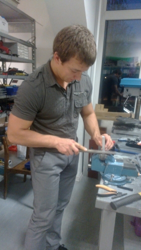
Thirdly, the rubber must be cast onto the metal shaft. This requires preparing three additional components – a properly-sized tube and two caps on it, shaped so that they would hold the shaft right in the middle of the tube. Making the caps meant some more lathe-work for Taavi.
Once the mold is done, the silicone (which comes in two separate components) is mixed, cast into the form onto the shaft, given several hours to harden and taken out of the form, hoping no ugly bubbles or unnecessary objects got caught in it during casting.
Finally, the shaft must be mounted into the ball bearings and geared to a motor (which, in turn, has to be mounted appropriately and connected to a pin of a microcontroller board).
The video below illustrates the functioning of a completed dribbler:
Laser cutting is good for making flat sheets, but not enough to produce 3D shapes. CNC (Computer Numerical Control) milling is the way to make those. As with laser cutting, you can order CNC services at a reasonable price nowadays. It was even easier for our team – Tartu University’s Institute of Technology has a mill available and Taavi knew how to use it.
Piece of a G-code program
The CNC machine is programmed using a special programming language – the G-code, where each instruction corresponds to some movement of the mill. Ironically, despite the obvious practical importance of this language, most programmers or computer scientists have probably never even heard of it. If you are one of them, take a minute to educate yourself and skim through the Wikipedia entry, at least.
Although the CNC code can in principle be generated by CAM systems straight from the 3D CAD-model, it was easier for us to write the program manually, as it allows to account for the specifics of the particular machine in our case.
In the video below, Taavi is running the code he wrote for cutting the coilgun box for the Telliskivi robot:
And if you think this is cool, you might want to take a look at what the expensive industrial CNC mills can do in the hands of expert programmers: (one), (two).
The first Robotex competition took place in 2001. Although I did not take part then, I remember observing with interest the progress of Tartu University teams. Looking back 10 years now, it is fascinating to see how much changed since.
One of this changes is the perhaps wide spread of affordable computerized manufacturing. Laser cutters and CNC milling machines have existed for years now, but it seems that in just the last 10 years has their use become accessible to pretty much anyone who needs it. The more recent 3D printing can’t go without mention – one can get a reasonable tabletop 3D printer at the price of a high-end laptop nowadays.
So for those of you who are new to this thing, here’s a brief example of how things work in the marvellous world where one does not need to know anything about saws and hammers in order to create hard metal objects.
Modeling the part
First, we use a CAD system (SolidWorks, in our case), to create a model of the part. This requires some knowledge of the CAD system, but it is not rocket science, really.
CAD model of a part
Ordering the part
Next, in order to order an actual part from this model, we need to create two files:
As in this particular part we would like the manufacturer to help us with the metal sheet bending, we also need to provide the technical drawing of the final part. The CAD system is quite helpful here too: it takes a couple of clicks to generate the drawing from the model:
Technical drawing
Note that depending on the manufacturer, additional files may be required in certain format as a specification, but in our case this was sufficient. You then send the specification to the manufacturer and wait. Most commercial manufacturers would typically produce parts in batches of at least 100 or so, so if you need just one, you would often have to come up with a personal arrangement.
The price range differs depending on the manufacturer (some have cheaper, less precise machines, some have better ones), chosen material (cutting thinner material requires less power) and personal arrangements. In particular, the total price of computerized manufacturing for the single part shown above, including material (1.5mm aluminium sheet), is less than €20, and can be significantly less, if you manage to get a good deal.
In order to plan the robot (e.g. choose the motors and plan the strength of the coilgun) as well as to implement the simulator, we needed to know the movement dynamics of the golf balls on the field. There is nothing special about their movement – we can safely assume that balls roll with a constant deceleration. The problem is, however, that no one seemed to be able to tell us, even approximately, what this deceleration was exactly.
So we went on and made a crude measurement using the camera, which, in retrospect, is fun to think about. Here’s how it was done.
Measuring ball movement
First, set up a straight path for the ball, marking the 0cm, 50cm, 100cm and 150cm points. We would then roll the ball along this path, measure the time when it passed the four points, and use the obtained numbers to fit the parameters of the equation:
s = v0 + v(t-t0) + 0.5a(t-t0)2
There are three unknowns here (v0, v, a) – that’s why we need three marks plus the starting mark (t0) for each measurement (i.e. for each ball run).
Next, we use a camera to film a number of such “ball runs” from the side. Finally, we manually examine the resulting video frames, writing out the time points at which the ball passed each of the marks.
As a side note, if anyone of you, dear readers, for some reason plans on doing something similar at some point of their life, here’s what you should do to find out the timestamps of the frames in a video:
Install the ffdshow codec. In FFDshow configuration switch on “OSD” (on-screen display) and on the corresponding settings screen put a checkmark near “Frame timestamps”.
Install Media player classic. In its configuration, switch off all “Internal Filters” and add as “External Filter” the ffdshow Video Decoder. After that, just play the video using this player. You will see frame timestamps and will be able to move frame-by-frame back and forth using the Ctrl+left/right keys.
A video frame of a moving ball
Obviously, this type of measurement is very crude, however for our purposes it is enough. After having manually “parsed” a video recording of five runs we obtain the following data table:
The rows here correspond to different runs and the columns – to the four marked points. The values in the cells are timestamps (in seconds from the start of the video).
At last, we fit the movement equation for each row to estimate the “a” parameter. We can do it using R, for example, as follows:
data = data.frame(T0 = c(15.244, 26.327, 35.219, 43.604, 51.963),
                  T1 = c(15.840, 26.651, 35.570, 44.080, 52.500),
                  T2 = c(16.598, 27.100, 36.020, 44.638, 53.182),
                  T3 = c(17.804, 27.566, 36.500, 45.260, 54.047));
for (i in 2:4) data[,i] = data[,i] - data[,1]
data$T0 = NULL
a = c()
for (i in 1:nrow(data)) {
  y = c(0.5, 1.0, 1.5)
  x = t(data[i,])
  x2 = t(data[i,]^2)/2
  m = lm(y~x + x2)
  a = c(a, m$coeff[3])
}

# Median and max a
print(median(a))
print(min(a))
From that we get that the median deceleration of the five runs is -0.15 m/s2 and the smallest estimated value was -0.25 m/s2.
Now we may use this value in the simulator and consider it when choosing the motors.
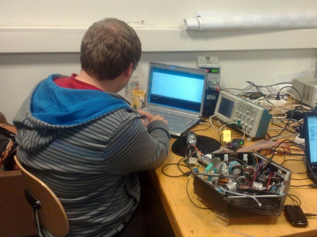
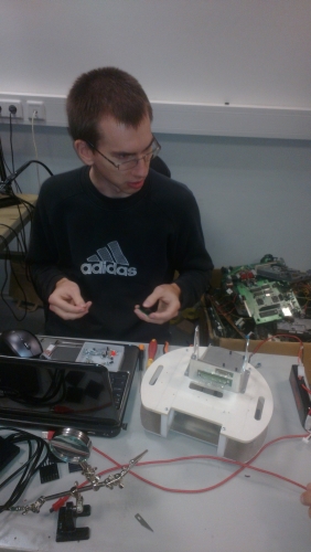
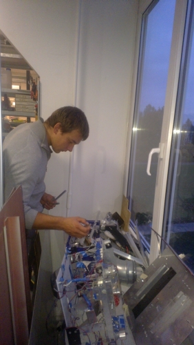
Night or day, there is always someone in the Tartu University’s physics department Digilabor, fiddling with their electromechanical babies. Here are some random shots from one evening when teams Nasty and Sidi were there.
Tõnis, doing brain surgery on the Sidi robot
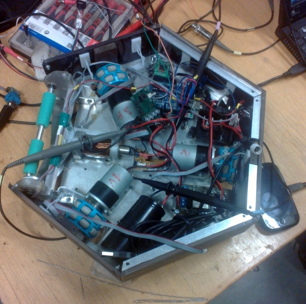
The Sidi robot on the operating table
Harti has taken the Sidi robot’s head off and is up to something
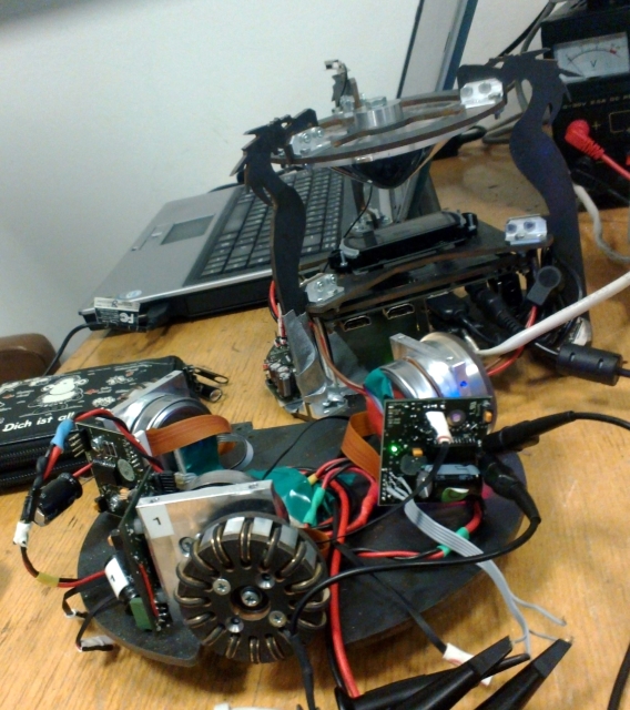
Tartu’s rock star team 18cm-hyperbolic-mirror-custom-omniwheels-CAD-magazine-award team Nasty robot in pieces
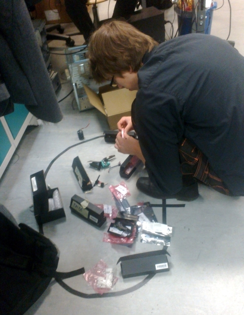
Looks like Mihkel has just burned something in the Nasty robot and looks for a replacement
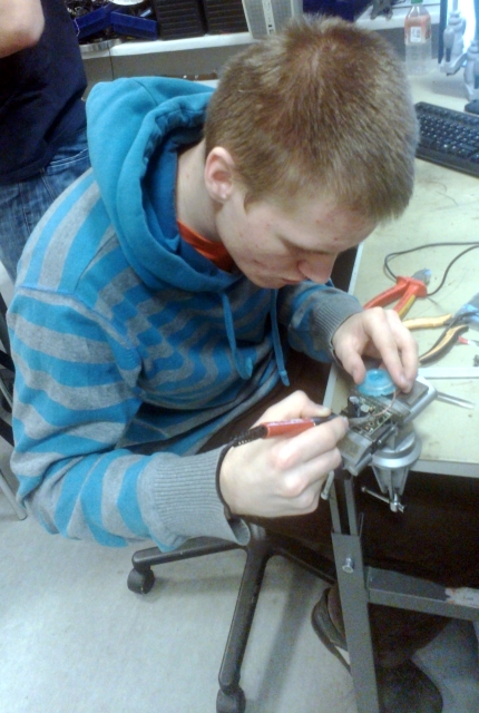
Karl is soldering a motor control PCB for the Nasty robot
Nasty’s motor control PCB rotating a brushless motor with an omniwheel
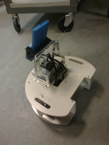
October 15th – we have the second floor’s plate (plastic laser cut by Tööstusplast) and the “tower” for the phone. We do not yet have the “proper” phone mount, but Taavi made a temporary one from whatever he found in the lab, and as a result we have a robot which already looks like the real thing and smells like victory.
The second floor with the “tower”
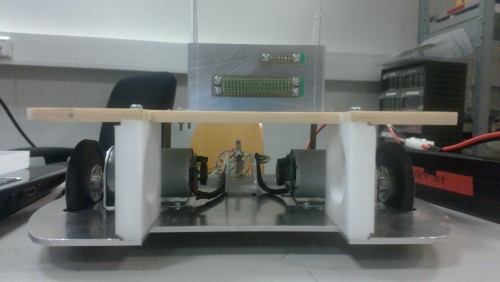
The first and the second floors together
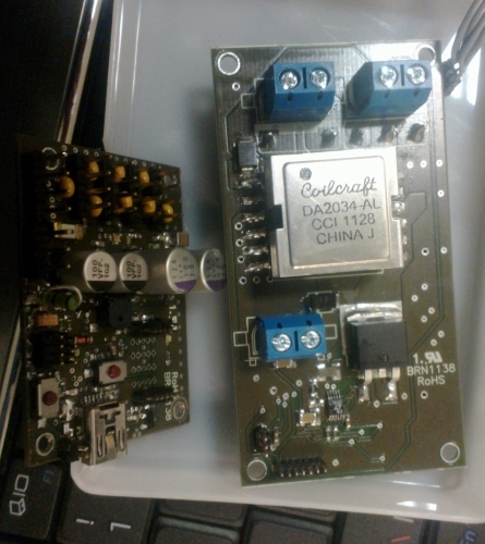
Electronics: The motor-control PCB (left) and the coilgun PCB (right)


")