All posts by Konstantin

Bluetooth

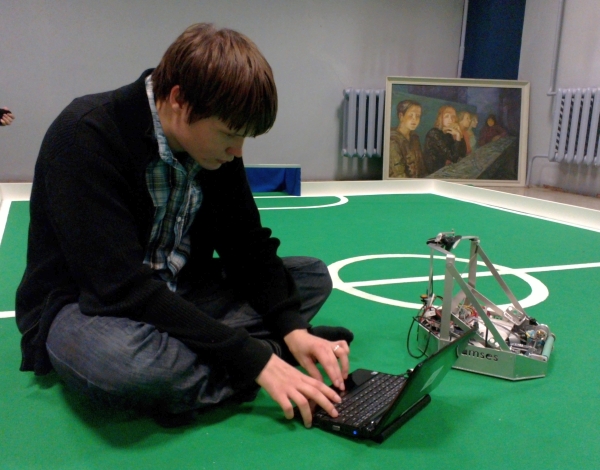
OK, so we have made the chassis with a couple of motors, a coilgun, a ball detector, and the electronic circuitry to control all of this. This makes up the “body” of our robot and what remains is the “brain”. As you should know already, the brain in our case is a Nokia smartphone. The brain needs to be constantly communicating with the body – sending movement and shooting commands and reading ball sensor and perhaps motor sensor data. As we explained in one of the first posts, we need to use the Bluetooth protocol for such communication.

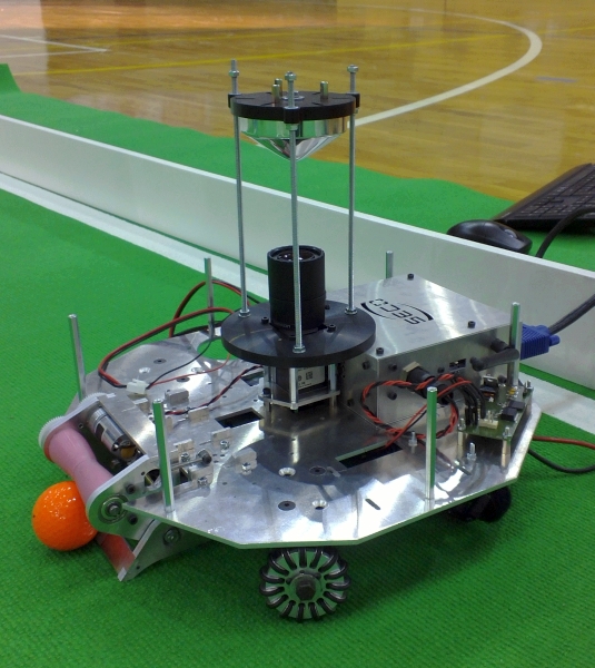
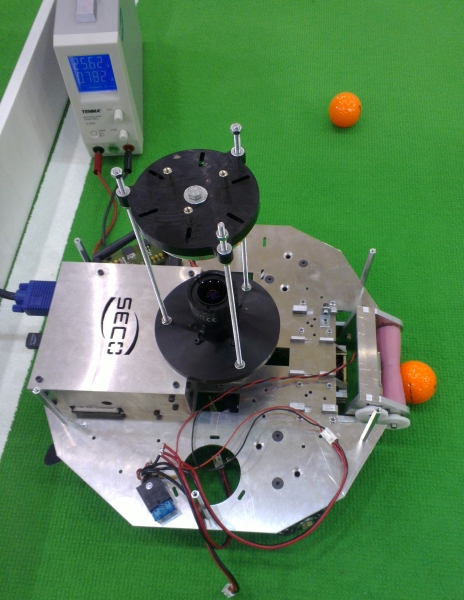
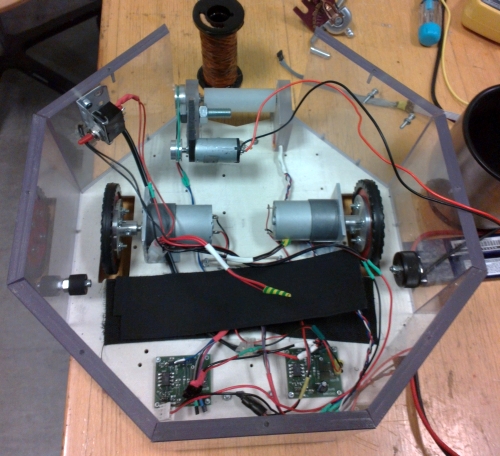
We thus had to purchase a separate module and connect it to our main microcontroller (attentive readers have already seen this module in one of the pictures). There is a fairly wide variety of Bluetooth modules available out there. Our criteria for choosing a suitable one were the following:

  • The module must have an integrated implementation of the full Bluetooth protocol stack. Bluetooth is a fairly complicated set of protocols, and there are some modules which only implement parts of it. The remaining parts would have to be implemented in software (i.e. in the microcontroller) and this would make our life difficult.
  • The module must use the UART protocol. This is the default serial protocol supported by our microcontroller. Most Bluetooth modules use it anyway.
  • The module must have a readable datasheet. Debugging a no-name module with no reference manual is not something we look for.
  • The module should be reasonably priced. Although ELFA is certainly not a place to look for “reasonably priced” things, we can use the knowledge that the cheapest module there (which happens to fit the previous criteria) costs €32.50.
  • Finally, the module might have some positive reviews on the internet.
BlueSMIRF Silver
BlueSMIRF Silver

SparkFun’s BlueSMIRF Silver happened to fit all of them (especially the last one), so we ordered it and so far it has been one of the less troublesome parts of our robot. Although it does have a detailed datasheet, pretty much none of that information was even needed, because the module does most of the work itself. All the microcontroller has to do is read and write bytes over the UART pins, to which the module is attached.

To read and write over UART we borrowed the code from the Teensy UART library and added a couple of simple wrappers around the low-level uart_getchar and uart_putchar methods. After this was done, we could complete the main loop of our robot’s microcontroller:

int main() {
    // ... initialization code ...

    char buf[32];

    while (true) {
        bool success = recv_command(buf, sizeof(buf));
        if (success) execute_command(buf);
    }
}

This function, together with the interrupt handlers mentioned in the post about motor control, is essentially all there is to our main microcontroller’s code.

Serial Communication and Interrupts

If you will be implementing a similar solution, beware of one particular hidden reef. The UART communication in Atmega uses interrupts to receive bytes. That is, every time a new byte arrives on the serial port, an interrupt handler is invoked. The code in this interrupt takes responsibility of storing the received byte into a buffer for further processing. While this interrupt is in process, no other interrupts will be invoked. For example, if during the reading of a byte a motor encoder happens to send a pulse, this pulse would not get counted, simply because the controller won’t be there waiting to catch it.

This issue is even worse the other way around – if the microcontroller happens to stay “too long” in one of the other interrupts, he might simply miss an incoming byte. As a result, weird things will start happening – the command “move” might get received as “mve” or worse still, a command separator character will be missed and two commands will be concatenated into one.

There is really no good solution to this problem besides being careful and not writing code which might stay too long in an interrupt handler. At one moment we had an interrupt handler like that (the one which performed the PID computation in a timer), and it resulted in a fairly large number of communication errors. Surprisingly, the problem nearly disappeared after we rewrote the computation from 32-bit integers to 16-bit integers. It turns out that an 8-bit microcontroller can spend too much time simply adding and multiplying 32-bit numbers.

Bluetooth and Latency

A final word of warning is related to latency. Although the communication speed for a Bluetooth connection is quite good (in our case it was actually limited by the UART’s 115 kbps), the latency is not. That is, although you might easily send up to 15 000 single-character commands per second on a UART+Bluetooth connection, if you require (and wait for) a response to each command, the actual throughput can be somewhere around 30-60 commands per second.

In fact, this particular problem (and the fact that we discovered it too late to go fixing) has been one of the main reasons why our robot was somewhat “slow” during aiming in the final competition. We focused a lot on keeping the vision processing speed at 30 frames per second as this was, according to general knowledge, the hardest part to get working fast. Unknowingly, we were at the same time unreasonably wasteful in communication. Whenever robot would have the ball in the dribbler, we would query the ball sensor too often. As we would also wait for sensor query command to respond before proceeding with computation, this (rather than the dreaded vision processing!), was the reason our actual processing speed went down to about 15-20 fps every time the robot was holding the ball. Those were, however, exactly the moments when the robot was aiming for the goal and needed as high a framerate as possible.

Operating the Coilgun

Now that we’ve figured out how to operate a motor, let us describe the second important electro-mechanical component of the robot – the coilgun. Previously, we have already discussed briefly the general idea and its mechanical realization. What remains are the minor implementation details.

Recollect that the general scheme of a coilgun (somewhat simplified, of course) is the following:

Coilgun
Coilgun

In order to make this scheme operable, we must replace the switches “Enable charge” and “Enable discharge” with transistors, connected to a microcontroller. In our case we had a separate microcontroller operating the coilgun, which means that we also needed to establish communication between the main controller and the coilgun controller. The resulting scheme is then, in principle, the following:

Coilgun control
Coilgun control

The task of the coilgun microcontroller is rather simple: receive signals from the main microcontroller and set its output pins A and B accordingly. Our robot’s coilgun controller implemented essentially the following four functions:

void enableCharge() {
    set_pin(PIN_A, 1); // Enable charging of the capacitor
}

void disableCharge() {
    set_pin(PIN_A, 0); // Disable charging of the capacitor
}

void kick() {
    set_pin(PIN_B, 1); // Start discharging capacitor
    delay_ms(5);       // Wait 5ms
    set_pin(PIN_B, 0); // Stop discharge
}

void dischargeSlowly() {
    for (int i = 0; i < 20; i++) {
       set_pin(PIN_B, 1);
       delay_ms(1);       // Discharge a bit
       set_pin(PIN_B, 0); // Let the kicker be pulled back
       delay_ms(5);
    }
}

The last function (dischargeSlowly) is there to allow a graceful shutdown of the robot, where the capacitor discharges without the kicker having to jerk hard.

The communication between the main microcontroller and the coilgun may be implemented using various protocols. Originally, our coilgun PCB was meant to be controlled via the SPI protocol, but during one of the mishaps the corresponding pins burned down and we ended up using a simpler solution, where three output pins of the main controller were directly connected to the input pins of the coilgun board. A command was sent by specifying its code using the first two pins and sending a pulse on the third one.

If you will ever be making your own coilgun…

It must be noted that the coilgun was perhaps the most complicated electromechanical part of our robot and as this blog tries to make things sound as simple as possible, it sweeps some details under the carpet. If you, dear reader, for some reason, will be going to build a coilgun yourself (perhaps when taking part in one of the next Robotex/Robocups), take your time to skim through the following sites first:

Safety notes

In order for the coilgun to be capable of hitting the ball with appropriate force, it must contain a reasonably large capacitor, and large capacitors can be dangerous. A 1.5mF capacitor, when charged to 250V, stores 0.0015·250² = 93.75 Joules of energy – something comparable to an energy of a 10kg brick falling from 1 meter’s height. If such a capacitor short-circuits, all this energy can get released in a single explosion, and you do not want your fingers to be nearby. Even if your fingers are spared, your electronics can get irreparably damaged.

In order to avoid a capacitor explosion (there were at least three of those among the Tartu teams during the two months leading to Robotex), keep in mind the following:

  • You should not short-circuit a capacitor. Obviusly, this will result in an immediate discharge of all its energy, which means an explosion. Of course, no one ever short-circuits a capacitor deliberately, but it is unexpectedly easy to do it accidentally.
  • You should never physically damage a capacitor. A damaged capacitor may short-circuit internally and explode for no apparent reason later on. Hence, if a capacitor falls on concrete floor once, beware when reusing it.
  • A capacitor must be used with appropriate voltages and connected in accordance to its polarity. Invalid voltage or polarity may damage it internally, which will lead to internal short-circuit.

To be more specific, here are some educational stories:

  • Some guys were debugging their PCB using a digital oscilloscope and touched a “positive” end of the capacitor with a “ground” probe of the oscilloscope. As a result, there was a short circuit through the ground, boom.
  • Other guys were trying to fix something using a screwdriver right on a working robot with a charged capacitor. Screwdriver touches the metal cover of the robot (which most probably was connected to the “ground”. of the electronics somewhere). Next, either due to a static discharge from the screwdriver, or due to its external potential acting to inversely polarize the capacitor, the boom happens.
    In fact, touching a working robot with a metal object is a bad idea for many more reasons. The two times when our team has managed to mess up the electronics were both related to someone trying to touch a working robot with a metal object. So beware.
  • Yet other guys have attached a capacitor to their robot using just Velcro tape. The robot starts spinning, the tape does not hold, the capacitor slips off and touches some of the electronics with its terminals. No boom, but all of the electronics burned down.


Operating a Motor

After we have chosen the motors and motor drivers, we must connect them to a microcontroller and control their rotation. How do we do that?

The Microcontroller

In our particular case we used a microcontroller chip mounted on a custom-printed circuit board together with the motor drivers, which we ended up not using anyway. Thus, our life would have actually been easier if, instead of using that custom board, we would just buy some well-known pre-made microcontroller board. The popular choices included Arduino, Teensy, Baby Orangutan, Basic STAMP, ARM mbed, TI LaunchPad, ST Discovery, and anything else you might google up using the keyword “microcontroller development board“. Hence, for simplicity, I shall avoid details specific to our case and assume the set-up with such a separate board.

For those of you not familiar with microcontrollers, it is enough to understand that a microcontroller is a just a black-box chip with several pins (those are the metal “legs” of the chip).The microcontroller can be programmed to set output voltage on some of the pins to certain values (usually either 0V, corresponding to “bit zero” or 5V, corresponding to “bit one”). It is also possible to sense input voltage on some other pins. Those two basic operations allow the microcontroller to communicate with other devices connected to it.

So, we have to connect some output pins of the microcontroller to the motor driver. Then, by setting appropriate output voltages on those pins, we shall be telling the motor driver to operate the motor as necessary. How exactly should the motor driver chip be connected and operated is specific to each chip, but in principle the assembly for one motor might look as follows:

Motor connection
Motor connection

Controlling the Motor

In the example above (which corresponds to the driver we used), two pins (A and B) are used to tell the driver in which direction to rotate the motor. The whole code for specifying rotation direction is thus as simple as:

if (rotate_forward) {
    set_pin(PIN_A, 1);
    set_pin(PIN_B, 0);
}
else {
    set_pin(PIN_A, 0);
    set_pin(PIN_B, 1);
}

Specifying rotation speed is just a bit trickier. For that we must produce a pulse width modulation (PWM) signal on pin X. This simply means quickly switching pin’s values between 0 and 1, so that on average the value “1” is kept a given fraction of time. A “full PWM” would mean keeping pin X at “1” all the time – in this case the motors would rotate with  their maximum speed. A “null-PWM” means keeping “0” all the time. This corresponds to motors not rotating. All values inbetween are also possible. If pin X is at value 1 one third of a time, the motors will rotate with approximately a third of their maximum speed.

PWM with 1/3 duty cycle

Most microcontrollers have built-in mechanisms for producing such a signal on some of the pins. We won’t delve into details of doing that – there are lots of tutorials out there already. For all practical purposes, the actual code for setting the motor speed boils down to

set_pwm_pin(PIN_X, speed); // speed = 0..255

Feedback

Are we done? No. Unfortunately, simply setting the motor rotation speed to a fixed number is not enough for precise control. For example, if we set the PWM speed inputs for both robot motors to the same value, despite all expectations, the robot will most probably not drive perfectly straight. Thus, to ensure exact control, we must constantly measure the actual rotation speed of the motor and adjust the PWM to keep the speed at a given value.

In order to measure motor rotation speed, our motor is equipped with a rotary encoder: a sensor, which generates pulses in accordance with the rotation. The faster the rotation – the more pulses are generated per second. To obtain this feedback information we first connect the motor encoder to an input pin of a microcontroller:

Motor with feedback
Motor with feedback

Next, we write a simple function that simply counts all pulses that come in on pin E:

ISR(INT0_vect) {
    pulse_count++;
}

Finally, we set up a timer interrupt that will regularly examine the current pulse_count value, compare it with some target value, and adaptively update the PWM signal on Pin X so that the target rotation speed is achieved:

ISR(TIMER0_COMPA_vect) {
    current_pulse_count = pulse_count;
    pulse_count = 0; // Reset pulse counter

    // Update pulse counter
    update_motor_speed(target_pulse_count, current_pulse_count);
}

PID controller

So how do we use the feedback and choose the appropriate PWM value to set for the motor speed in order to keep up with the target pulse count? This simple question has a whole discipline dedicated to answer it, known as control theory. The easiest answer that control theory provides us here is the PID controller.

The idea of a PID controller is generic and simple: we first measure the discrepancy between the target pulse count and the actual measured pulse count (the error):

error = (target_pulse_count - current_pulse_count);

In addition, we keep track of the error, accumulated over multiple iterations of the algorithm, and the difference between the error of the previous iteration and this iteration:

error_i = error_i + error;
error_d = error - prev_error;

The actual input to the motor driver is now computed as a linear combination of these three error values with some experimentally determined coefficients P, I and D:

new_pwm = P*error + I*error_i + D*error_d;

If the parameters are chosen well, the PID controller will magically keep the motor turning at the necessary speed.

So, to summarize the above, the update_motor_speed function may look approximately as follows:

void update_motor_speed(int target, int current) {
    error = (target - current);
    error_i = error_i + error;
    // Prevent the integral term from growing too large
    if (error_i > max_error_i) error_i = max_error_i;
    if (error_i < min_error_i) error_i = min_error_i;
    error_d = error - prev_error;
    prev_error = error;
    new_pwm = P*error + I*error_i + D*error_d;
    set_pwm_pin(PIN_X, new_pwm);
}

Our actual function was somewhat more complicated and included a couple of specific hacks and improvements, but the gist is still there.

Summary

To summarize, here is what you need to do to properly operate a motor:

  • Connect the microcontroller’s output pins to a motor driver, and the motor driver to a motor.
  • Use pins “A” and “B” (or whatever the motor driver specification requires) to set motor rotation direction.
  • Connect the motor’s rotary encoder sensor to an input pin “E” of a microcontroller.
  • Make sure the microcontroller is counting the pulses on pin “E”.
  • Set up a timer, that reads the counted pulses and updates the PWM parameters on pin “X” to match the “target_pulse_count“.

The same logic applies for the second motor.

But where do the motor direction and values of target_pulse_count come from? Those are specified by the higher logic, running in the phone, of course. We’ll get to that eventually.


The Motors

The parts of the robot, that have turned out to be one of the trickiest for us, were the motors. There are three motors in our robot – two for the wheels and one for the dribbler, and all of them have been causing headaches.

Choosing the Motors

The variety of motors one can choose for the wheels of a robot is staggering. How to choose the right one? Here’s how we went about it.

The first decision we had to make is whether to use a brushless vs brushed motor. The former type is typically more powerful, more expensive, and requires somewhat more experience to operate. The latter type is what most would call a “usual” motor. Having no prior experience with brushless motors and no desire to spend extra money, we went with the simpler option.

Next, we have to pick a particular motor. Two main functional characteristics play a role here:

  • Motor rotation speed – this will specify the max speed at which the robot will be capable of moving.
  • Motor torque – this will define the acceleration the robot will be capable of achieving.

The theory goes approximately as follows. Start by finding the necessary rotation speed. We know that the diameter of the wheels of our robot is 6cm. We would like the robot to be capable of moving at a maximum speed of about 1 m/s. That means, the motor must be capable of rotating with speed 1 / 0.06π ≈  5.3 revolutions per second, i.e. about 320 rpm. If we give it a little slack, we might be looking for a motor with free rotation speed of about 350-450rpm.

Next, let us compute the torque. Ideally, we might be willing for our robot to be capable of accelerating to the speed of 1m/s in about half a second, i.e. the maximum acceleration for the robot must be about 2m/s². The weight of our robot, fully assembled, is about 3kg, hence the motors will need to provide a force (F=ma) of at least 3·2 = 6 Newtons. In particular, 3 Newtons is the contribution that we expect from each motor. We also have to account for friction, and here we just blindly say we need about twice the force, i.e. 6 N from each motor. If our wheels would have a radius of 1 meter, we would need a motor with a torque of exactly 6 N·m to achieve that. Our wheels have a radius of 3cm, however, hence we would like a motor with a torque of about 6·0.03 = 0.18 N·m. Depending on the manufacturer, the motor may either be specified in terms of “rated torque” – this is a constant torque the motor is capable of providing for long periods of time, or “stall torque” – this is the maximum torque the motor provides when stalled. The stall torque is typically at least twice the rated torque, hence, according to our computations above, we might want a motor with a rated torque about 0.2 N·m or a stall torque at least 0.4 N·m.

Pololu motor
Pololu motor

After having scouted the web from end to end, we ended up ordering a pair of these and a pair of these motors from Pololu. Besides fitting our specification, the motors have a reasonable size (some alternatives were inconveniently large to fit into the robot) and have a rotary encoder built-in, which is a feature worth paying a couple of extra euros for. Pololu also sells useful accessories, such as wheels and wheel attachment hubs, which we also ordered. It turned out the attachment hubs we chose were not suitable for the 6cm Pololu wheels, though, so we ended up lathing our own wheels but still using the tires.

The Motor Driver Problem

The important feature of a motor is its stall current. This is the current that the motor consumes when stalled, i.e. exerting maximum torque. This happens when the motor is just about to start rotating, when someone prevents the motor from rotating freely (e.g., the robot has bumped into a wall) or when the robot is trying to accelerate. The motors we ordered have their stall current specified at 5A. However, the motor drivers we had to use on our motor control PCB (designed last year for Tartu’s last year’s robots), were only meant for 2.8A or smaller currents. (In case you already forgot, this post explains what is a motor driver). “Ah well, let’s just try and see what happens, maybe the drivers will just burn down”, we thought, and we tried. Unfortunately for us, the drivers did not burn down.

They kind-of worked, but worked badly. In order to run the motors at smaller speeds we had to use weird hacks, which are not worth delving into here, and in the end, the motors still wouldn’t behave predictably. After about a month of suffering and making us come up with ugly hacks, the drivers did finally burn down, and it was good. Because by that time we have already ordered a new, more powerful pair of drivers, and needed that final push to have those installed. As soon as we got the normal drivers set up, motors started working as necessary, and life became beautiful again.

Burned drivers
Burned drivers

The picture below shows the lower side of our motor control PCB. The three empty spots are the places where the three original motor drivers have been (the board was originally designed to accomodate four drivers, to be used with four-wheeled robots). One of the drivers burned down when we touched a working robot with a screwdriver (separate story). Two other ones burned for some reason later. The last driver is still sitting there, and it was used to control the dribbler motor, but eventually it also burned.

The moral of this story is simple: if you use powerful motors, use powerful motor drivers.

The Dribbler Motor Problem

As mentioned above, we were using the remaining driver to control the dribbler motor (so that it would be possible to choose the speed at which it would be rotating). However, we had bad luck with this one too. Despite the fact that the dribbler motor was not trying to consume too much current, the driver for it managed to burn down three times for no clear reason (some local gurus suspect that the motor was too “low-quality” for the driver, in the sense that its brushes produced too much spark discharges when switching). So in the end, we got tired of replacing the driver over and over and had the dribbler motor connected directly to the battery via a button. It was a very good choice and I am sorry we didn’t make it in the very beginning. So let me leave you another suggestion, dear reader: if you have a choice between a simple button and a complicated electronic microchip (such as a motor driver) strongly prefer the former!

The last remark is in order. Some of the Tartu’s other teams tried using brushless motors for the dribbler (simply because those were available), but as far as I’ve seen this has caused them way more trouble than it was worth. So if you, dear reader, plan on making a soccer robot, do not use a brushless motor for the dribbler. Just take any generic reasonably-sized brushed motor that you will find lying around in the lab, connect it with a button, and that’s it, you’re done. Tartu team Sidi had it done this way and, it seems, did not have any problem with their dribbler at all.

Once the motors are connected and running, we must somehow control them from the microcontroller. We’ll leave it as a topic of a later post.

Robotex 2011

So, the last three weeks were full of hectic preparations to what culminated in this weekend’s Robotex competition. Our team was incredibly lucky and did just great, winning the fourth place out of 16 participants, beaten only by the three teams from IT College. Considering that the IT College guys have been polishing their three more-or-less similarly designed robots for three consecutive years under the careful supervision of an experienced leader, we do not feel a single bit disappointed to grant them the fair victory. Telliskivi fought its best, losing to the overall winner with a close score of just 5:6.

The main factor which gave the ITC robots a defining advantage was their superiority in speed. This is not something unsurpassable – there were just technical reasons why Telliskivi was tuned to a “slower” setting for the competition, and we’ll discuss this in a later post, now that we finally have time to go on describing the ins and outs of our robot.

We are waiting for the Robotex organizers to put the competition videos out on their web – those are really fun to watch. So far, let me just share a couple of my own shots.

The competition-ready robot

Just a day before Robotex, on Friday, we received the final cuts for the transparent plastic cover of our robot.

Telliskivi, Friday, Nov 23rd.

On Saturday, we also found out that the horizontal bar on the goals will be attached firmly, so we added a couple of “frames” to preserve the phone in case the robot decides to drive into the goal (which we now could afford to allow in the algorithm).

Telliskivi, competition-ready

Nights before Robotex

Robotex is known for its promise of sleepless nights, and that promise was fulfilled. In fact, the bulk of the most important code was actually written during the last two nights. Something tells me it is not just our team who had it this way. Here’s how the competitor’s area looked at 3AM on the night before competition. Things didn’t change much all the way through to 8AM – there were still people working hard on the last-moment fixes.

Telliskivi’s first round
The only round I managed to get on my camera was our first game. It was easy to win – the opponent was extravagant, but non-aggressive. The opponent’s name was “Ventikas”, it was made by kids from the Kullo hobby club, and the sly trick it relied upon was to be large, stand at its own goal and blow air in three directions diverting the balls away from the goal. Unfortunately, the fan was not strong enough, otherwise it might turn out to be an unexpectedly hard opponent to beat. Note the careful aiming Telliskivi is making to get the ball exactly into the goal – at this point the judge asked me to stop filming as he suspected we might be remote-controlling it. That’s what good AI is all about – it looks like a human is behind it.

Telliskivi on TV

On the day before Robotex we actually got to show off our robot briefly on the early morning show on the national TV. Footage here (starting at 1:11:40).

Setting up the Camera


Camera and image processing are crucial components of a successful soccer robot. Consequently, before we could even start to build our robot we had to make sure the camera of the N9 won’t bring any unexpected surprises. In particular, the important questions were:

  • Is the angle of view of the camera reasonably wide? Can we position the camera to see the whole field?
  • What about camera resolution. If we position a ball at the far end of the field (~5 meters away) will it still be discernible (i.e. at least 3-4 pixels in size)?
  • Can it happen that the frames are too blurry when the robot moves?
  • At what frame rate is it possible to receive and process frames?

Answering those questions is a matter of several simple checks. Here’s how it went back then.

Resolution and Angle of View

The camera at N9 is capable of providing video at a framerate of about 30Hz with different resolutions, starting from 320×240 up to 1280×720. Among those, there three options which make sense for fast video processing: 320×240, 640×480 and 848×480. The first two are essentially equivalent (one is just twice the size of the other). The third option differs in terms of aspect ratio, and its horizontal and vertical angles of view. The difference is illustrated by the picture below, which shows a measure tape shot from a distance of 10cm.

Different angles of view

We can see that the resolution 848×480 provides just a slightly larger vertical angle of view than 640×480 (102mm vs 97mm) at the price of significantly reduced horizontal angle of view (65mm vs 86mm). Consequently, we decided to stick with the 640×480 resolution.

Camera positioning
Phone mounting angle

From the picture we can also estimate the angle of view, which is 2*arctan(97/200) ~ 52 degrees vertical and 2*arctan(86/200) ~ 46.5 degrees horizontal. Repeating this crude measurement produced somewhat varying results, with the horizontal angle being as low as 40 and the vertical as large as 60 degrees.

Knowledge that the vertical angle of view is 60 degrees suggested that the phone should also be mounted at around 60 degrees – this provided the full view of the field. As we also needed to see the ball in front of the robot, we had to mount the phone somewhat to the back.

Image Processing Speed

The first code we implemented was just reading camera frames and drawing them on the screen. The code could run nicely at 30 frames per second. Additional simple image operations, such as classifying pixels by colors also worked fine at this rate. Something more complicated and requiring multiple passes over the image, however, could easily drag the framerate down to 20 or 10 fps, hence we knew early on that we had to be careful here. So far it seems that we managed to keep our image processing fast enough to be able to work at 25-30 fps, but this is a topic of a future post.

Camera Speed

One reason why the Playstation 3 Eye camera is popular among Robotex teams is that it can produce 120 frames per second. And it is not the framerate itself, which is important (it is fairly hard to do image processing at this rate even on the fastest CPUs). The important part is that the frames are shot faster and thus do not blur as much when the robot moves. So what about our 30 fps camera? Can it be so blurry as to be impractical? We used our NXT prototype robot (at the time, we did not have our “real” robot, not even as a 3D model) and filmed its view as it drove forward (at 0.4 m/s) or rotated (at about 0.7 revolutions per second). The result is shown below:

Moving forward
Moving forward
Rotating
Rotating

The results are quite enlightening. Firstly, we see that there is no blurring problems with the forward movement. What concerns rotation, however, it is indeed true that even for a moderate rotation speed, anything further away than 50cm or so blurs to be indistinguishable. It is easy to understand, however, that this is not so much a limitation of a 30fps camera but rather a property of rotation itself. At just one revolution per second, objects even a meter away are already flying through the picture frame at 6.28 m/s. Even a 120fps camera won’t help here.

Size of the Ball in Pixels

OK, next question. How large is the ball at different distances? To answer that, we made a number of shots with the ball at different distances from the camera and measured the size of the ball in pixels. The results are the following:

Distance to ball (mm) 100 200 300 400 500 600 700 800 900 1000
Ball diameter in pixels (px) 190 105 70 55 45 37 33 29 26 22
Distance vs Pixel size

This data can be described fairly well using the following equation (the reasons for this are a topic of a later post):

PixelSize = 23400/(21.5 + DistanceMm)

Two observations are in order here. Firstly, a ball at distance 5m will have a pixel size of about 4.65 pixels, which not too bad. Note that it would be bad, though, if we were to use a resolution of 320×240, as then it would be just 2 pixels. Add some blur or shadows and the ball becomes especially hard to detect. Secondly, and more importantly, if we decide to use such an equation to determine the distance to the ball from its pixel size, we have to expect fairly large errors for balls that are further away than a couple of meters.

So that’s it. Now we’ve got a feel of the camera and ready for actual image processing.

RoboCup

Tallinn’s Robotex competition is about a single robot trying to hit all balls into the goal. Its “older brother”, the RoboCup, is about many robots chasing one ball, just like in real soccer. Doesn’t it look amazing?

Telliskivi’s robotic siblings/colleagues/opponents, part IV – Tallinn teams

Yesterday we had a chance to go to Tallinn to “practice” in the same room and with the same lighting that will be during the actual competition. There was also a “test competition” on which our robot, who lacked most of the relevant algorithmic logic, did not score a single goal. None the less, it could practice driving along the field in random directions, fighting for the ball with an opponent, and shooting a ball in the wall of the playing field, having confused it with a goal.

In the meantime, I made a couple of shots of the other robots (by IT college and TTU temas). Please excuse me for not being capable of properly identifying them. If you happen to know the names, do tell me, I’ll update the post. I might also have missed some of the robots from yesterday’s event.

Telliskivi’s robotic siblings/colleagues/opponents, part III – Advanced league

The second group of guys in Tartu are the “gurus”. They have already done at least one Robotex, and their current aim is not so much to make a baseline working device, but rather to create something fun and unusual. This takes them way more than a couple of months.

First is team Nasty, who are making an extra-cute tiny robot with a hyperbolic mirror (this way one camera can see the whole field). Their robot design was even published in a SolidWorks-themed magazine (lost the link to it, sorry).


Team Nasty robot "Mall2"
Mihkel showing off Mall2
Ramses vs Mall2
Ramses vs Mall2

If team Nasty is aiming for a smallest possible size, another team (not sure about the name), is making a hyperbolic-mirror based robot which is as large as it can get. Its weight is going to be close to the upper allowed limit of 8kg. Unfortunately, I did not manage to get a shot of this robot in its assembled shape, but here’s the view of its lower base plate during maintenance:

The baseplate of a heavyweight robot

The third guru here is Matis, who is working on something which has huge wheels, two kilowatt-or-so powerful motors and can drive around at 5-10 m/s, if not more. This robot is in its early stages yet, so it does not have anything besides the motors and wheels yet. As usual, I could not even get a good shot of it

Chassis of Matis's robot

Finally, there is a robot that, I am sure, is going to be everyone’s favourite, once it steps up onto the Robotex field (which, unfortunately is not happening this year yet). This is the legged spider by team “polügoon Z”.

Spider robot
Spider robot
Spider robot
Spider robot
Omnivision camera on the bottom of the spider

The best part of it is that the Spider robot team maintains an awesome blog, covering everything about their robot’s insides and outsides.

Telliskivi’s robotic siblings/colleagues/opponents, part II – Beginners league

There are two types of Robotex robot builders in Tartu – the beginners and the “old sharks”. The first ones are those guys who come in September with no previous experience, and struggle with the simplest things to have the simplest possible solution working by the end of November, when the competition happens. We are one of such teams. Besides us, there are beginner-league teams named Spirit, Sidi, and EKRS. Although I’m not good at being with a camera at the right moment in the right place, I did manage to get some shots.